
How do you customize and render a Diagram in Axogram?
Learn how to customize your diagram, navigate the scene, adjust environment settings, and render your final image in Axogram.

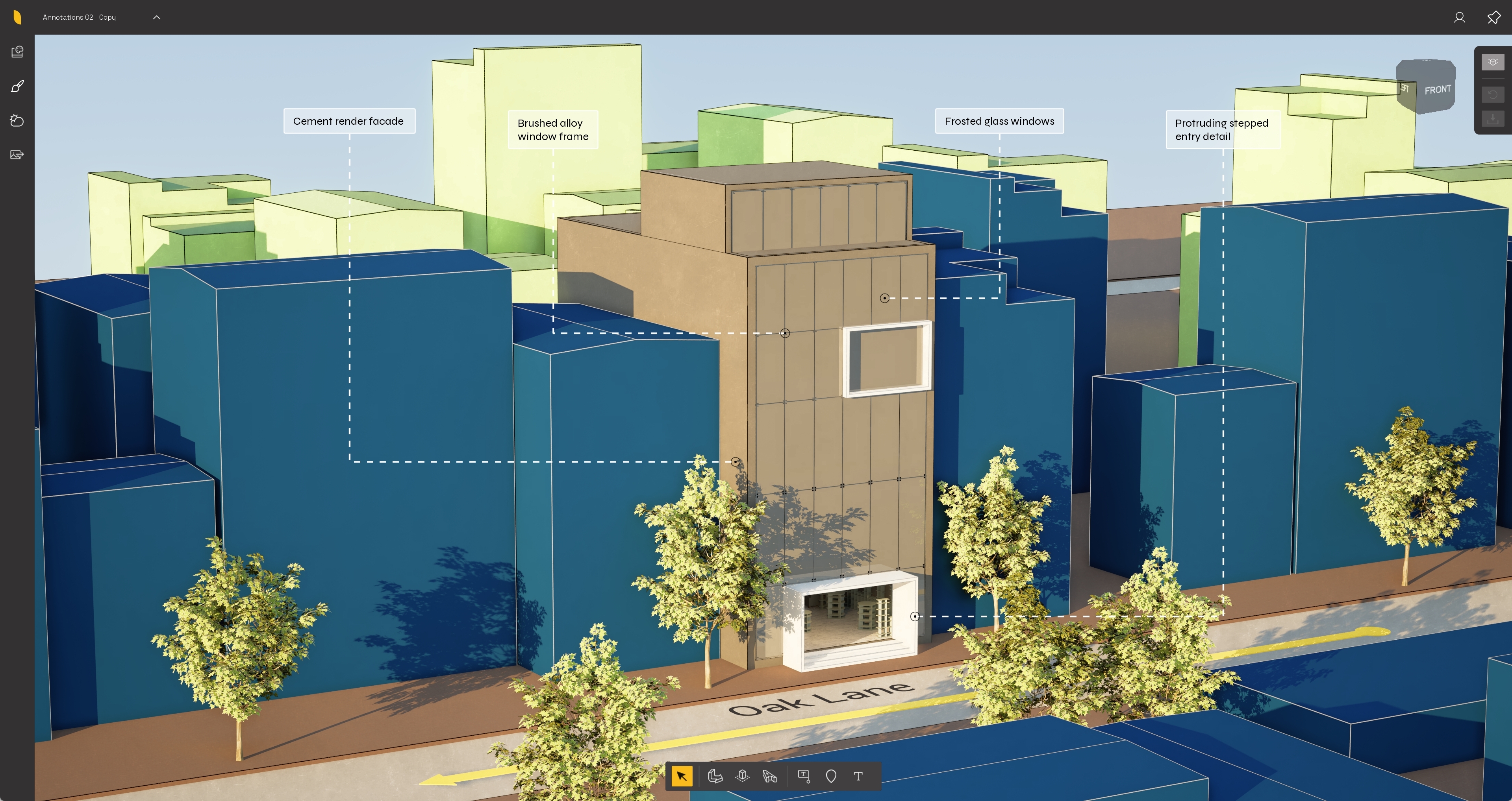
Axogram includes several workspace controls for working with a Diagram. The left toolbar controls the Diagram’s visual style, materials, environment, and rendering options. The camera and view controls on the right help you navigate the %%Scene%% and adjust the view. This article explains these main controls and how they affect the final result.
Menu:
Diagram Controls: Saving and Camera:
| 1. Visual Styles | 5. Saving and Managing Diagrams |
|
|||
| 2. Styles Mixer | |||||
| 3. Environment | |||||
|
7. View Cube |
For tools used to add and edit objects, such as annotations, markers, 3D Text, 3D Arrows, and Zones, see:
-
Knowledge Base: How do you annotate diagrams in Axogram?
For a full list of camera/navigation and keyboard shortcuts, see:
- Knowledge Base: Keyboard Shortcuts in Axogram
Important: Axogram does not create a separate project file. Your Diagrams are saved with your CAD project file.
When you save or share the CAD project file, the Axogram Diagrams are included with it. Another user can access the Diagrams when they open the project and sign in with a %%Lumion Account%% that has access to Axogram. A free Axogram account is sufficient.
![]()
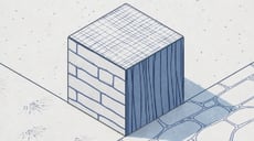
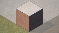
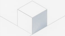
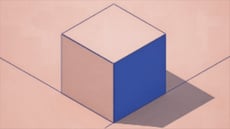
%%Styles%% let you quickly apply a diagrammatic appearance to the entire %%Scene%%. Select a %%Style%% to change the overall colors, shading, edges, and visual treatment of the model. Each %%Style%% provides a different starting point while retaining controls that let you further adjust its appearance.
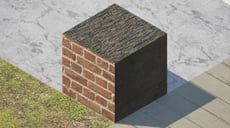
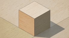
There are eight %%Styles%% available:
|
Clay |
Realistic |
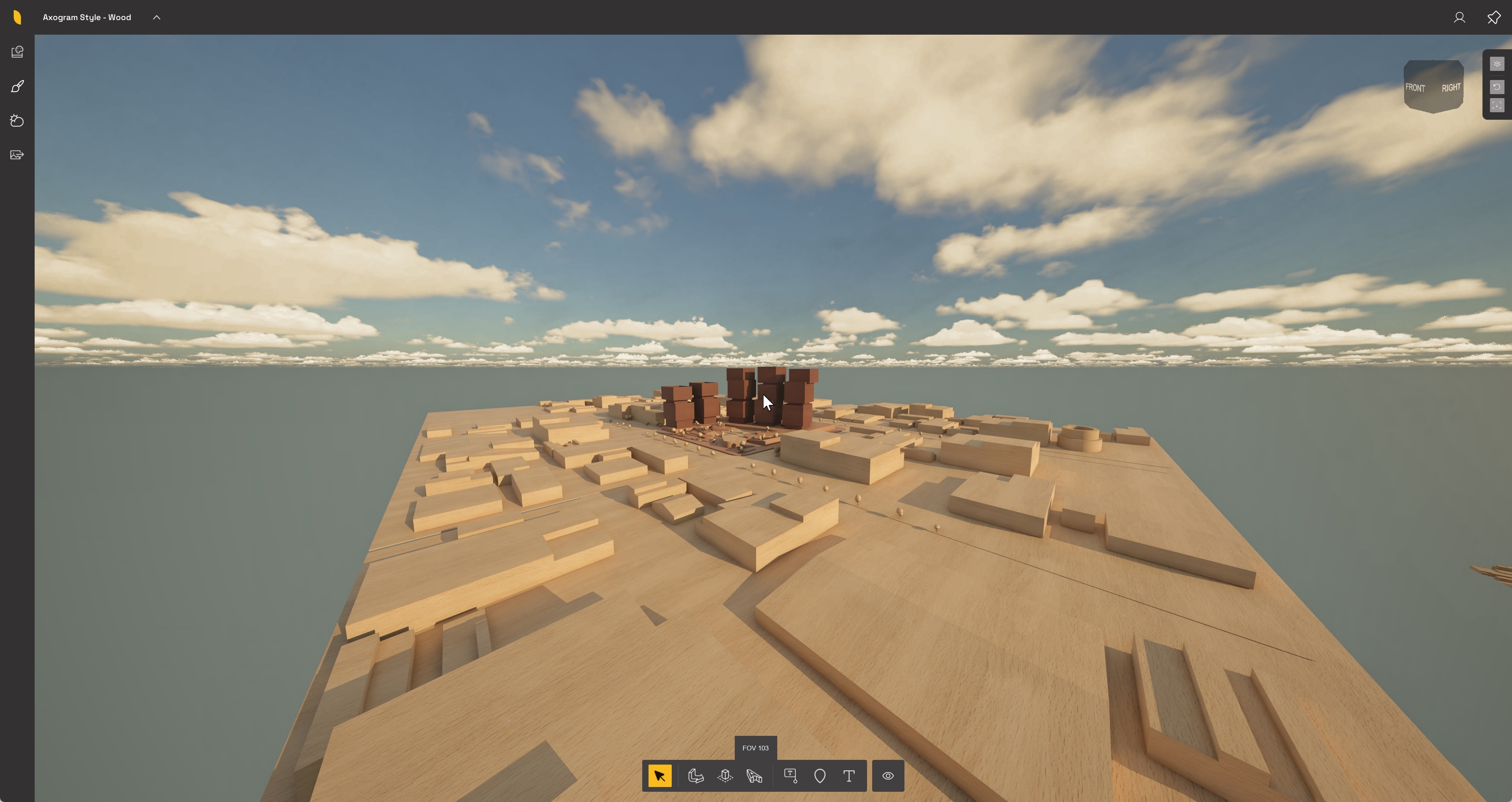
Wood |
Ink |
|
|
|
|
|
|
Soft Vibe |
Polar |
Dual Tone |
Blueprint |
|
|
|
|
|
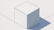
1.1 Style Settings
After selecting a Style, use the Basic settings to customize its appearance. The available settings can vary depending on the selected Style.

![]()
1.1.1 Scale
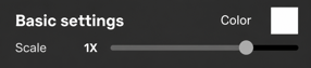
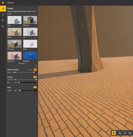
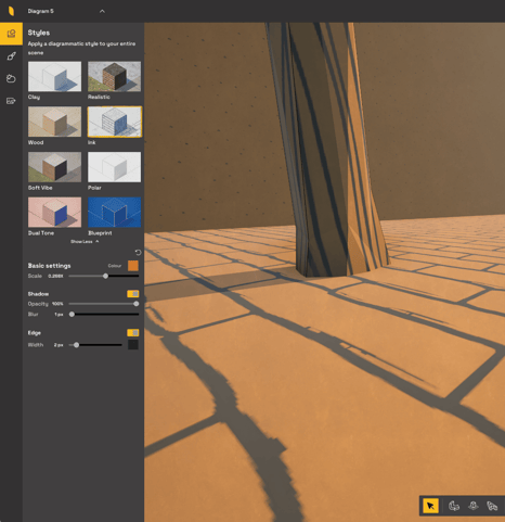
Depending on the %%Style%% you choose, you can adjust the scale of the material or pattern of the surfaces.
1.1.2 Color Picker (Advanced Menu)
![]() |
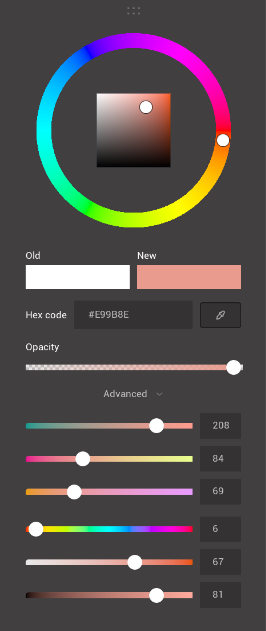
Select a color picker to open the Color Picker. Use the color wheel and color field to visually select a color, or enter a specific Hex code when an exact color is required. Changes made using the color wheel, Hex code, or Advanced controls are automatically reflected in the other color values.
Expand Advanced for more precise color control, giving you access to each channel individually.
|
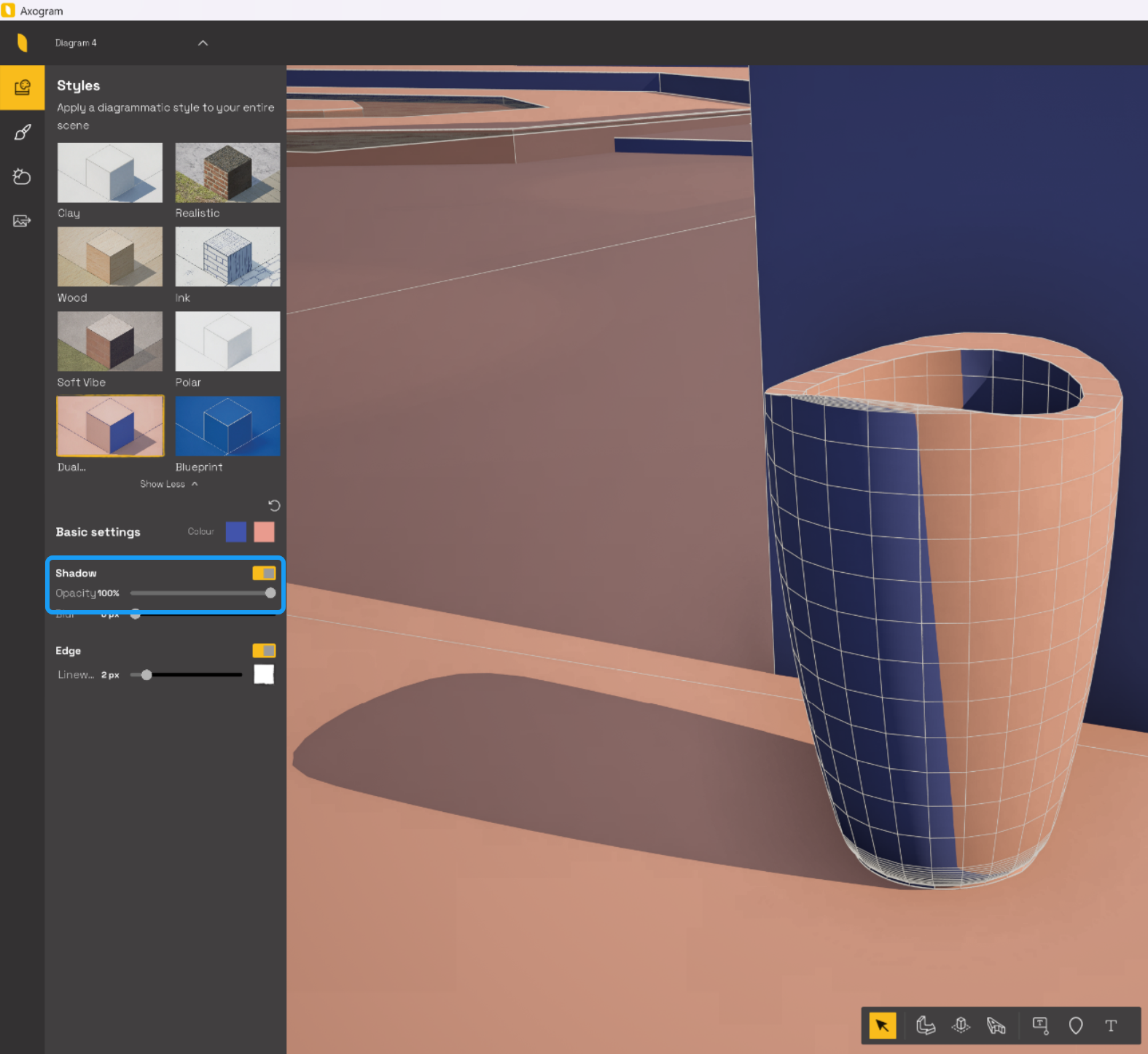
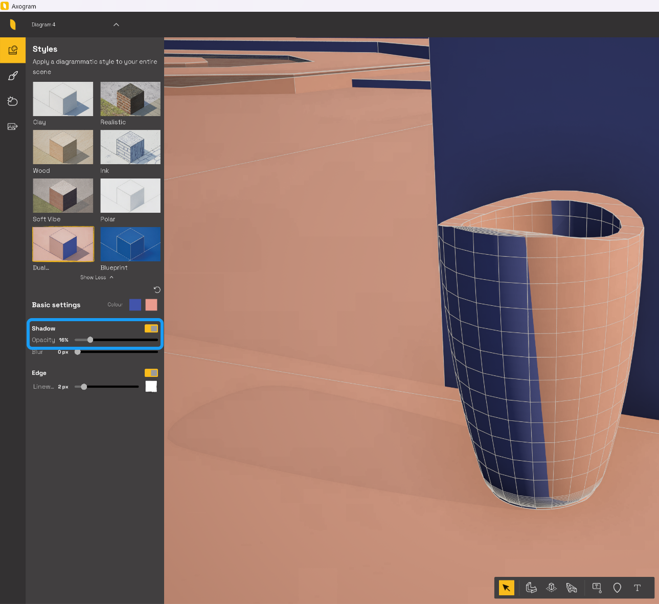
1.1.3 Shadow
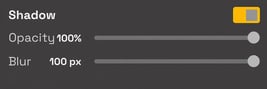
Toggle this On or Off to enable shadows as needed. This option has 2 settings: Opacity and Blur.
1.1.4 Opacity
Use Opacity to control the strength of the shadows. At higher values, shadows appear darker and more prominent, emphasizing the model’s depth. Reducing Opacity makes the shadows lighter and less visible, while they can still remain defined.
1.1.5 Blur
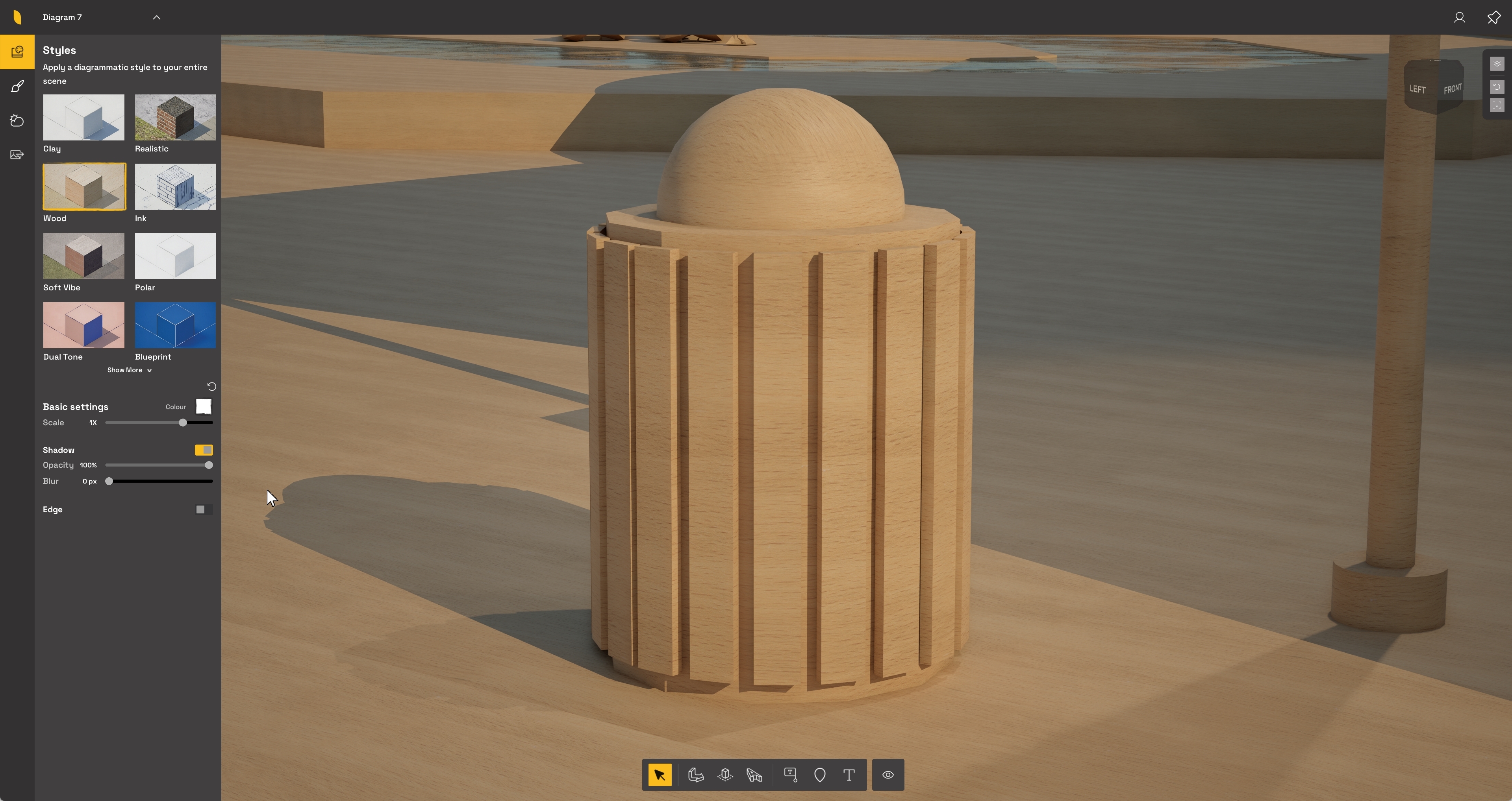
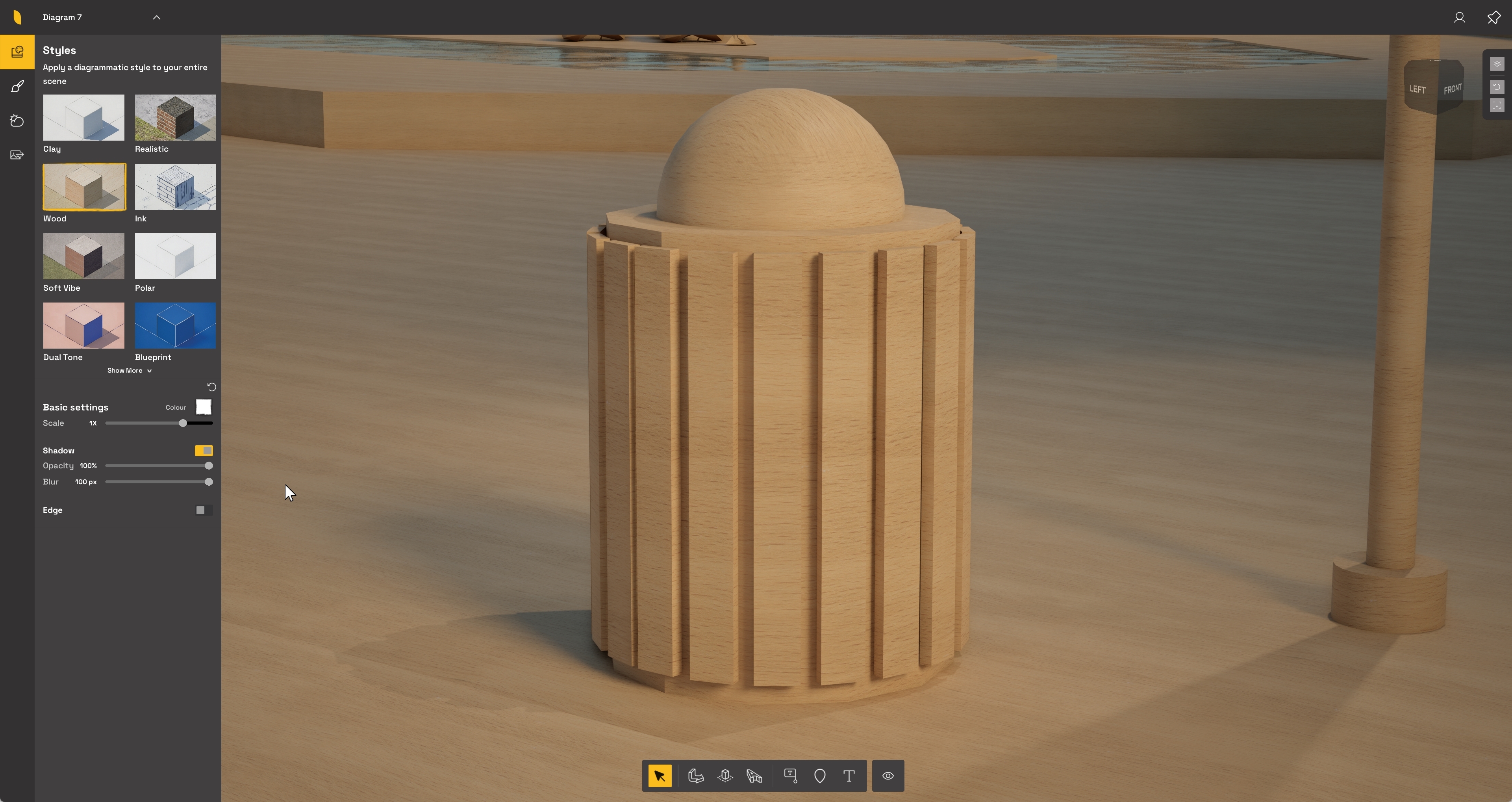
Use Blur to control how sharp or soft the shadow edges appear. Lower values create more defined shadows (as in the screenshots above), while higher values soften and spread the shadow edges.
1.1.6 Edge
Use Width to control the thickness of the lines used to define the model's edges. A convenient toggle lets you turn the edge outlines on or off as needed.
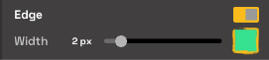
Increasing the value makes the geometry more strongly outlined, while lower values produce finer, less prominent edges. This scale ranges from 1px to 10px. Select the color picker to change the color of the edge lines.
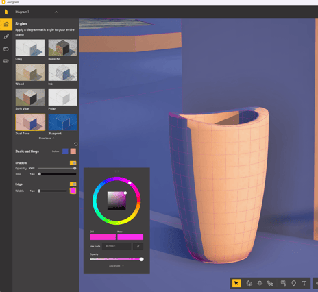
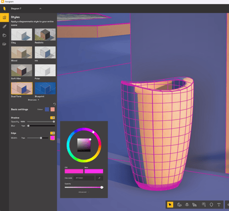
Note: Some controls may not be available for every Style, depending on the visual treatment used by that Style.
After choosing an overall Style, you can use the Style Mixer to apply different Styles to specific materials in your model. The Style Mixer starts empty, but once you select a material, you can choose one of the eight available Styles and apply it to that material. You can then adjust the color to suit, letting you mix Styles across one, several, or all materials in the Diagram.
Tip: Be sure that if you want to separate the Styles for each material, you will need to have a different material name assigned inside your CAD program.
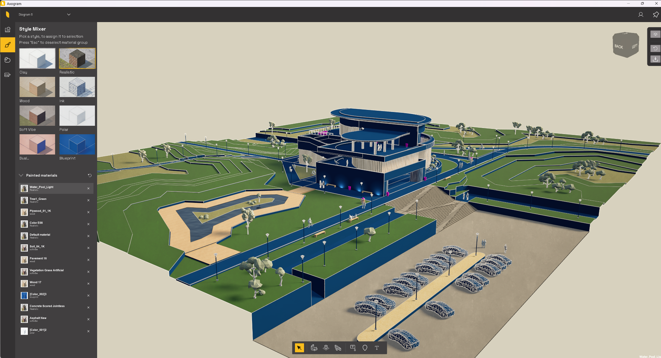
This gives you greater creative control over the presentation. You might highlight a particular wall or material, draw the client’s attention to a specific area, or combine styles to showcase the project more effectively.
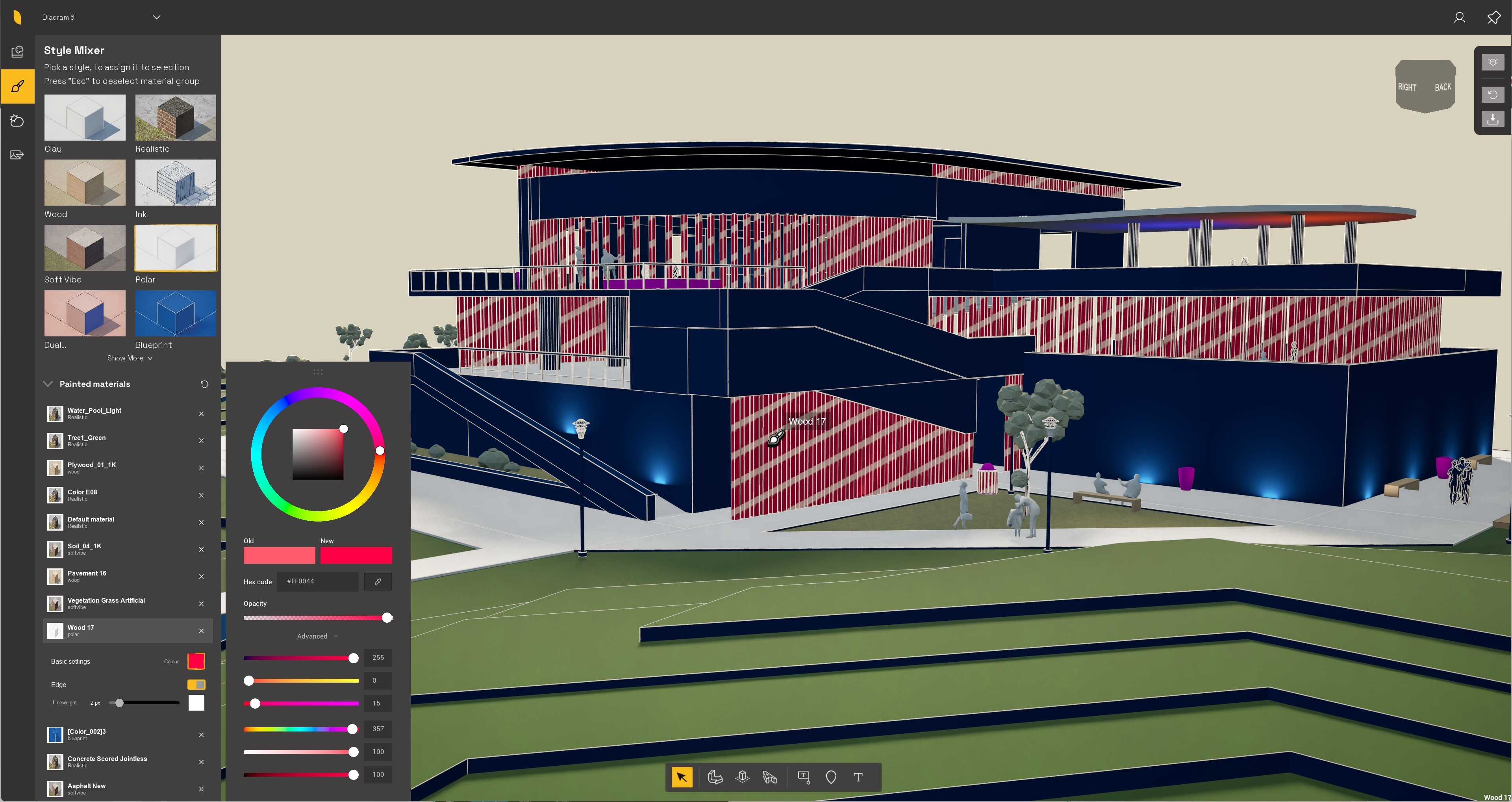
When selecting a material, you will see the highlighting on the corresponding materials that you are going to apply the Style to. Each selected material includes familiar styling controls, such as Basic Settings, Edge, Width, and other options found in Styles.
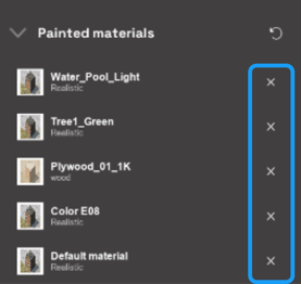
As each new Style is applied to a new material, each selection will appear under Painted materials. To remove the Style from a single material, click the icon "× " beside its corresponding entry.
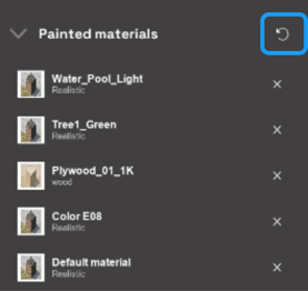
To remove all painted material Styles at once, click the icon ⟲ "Reset all overrides" at the top of the list.
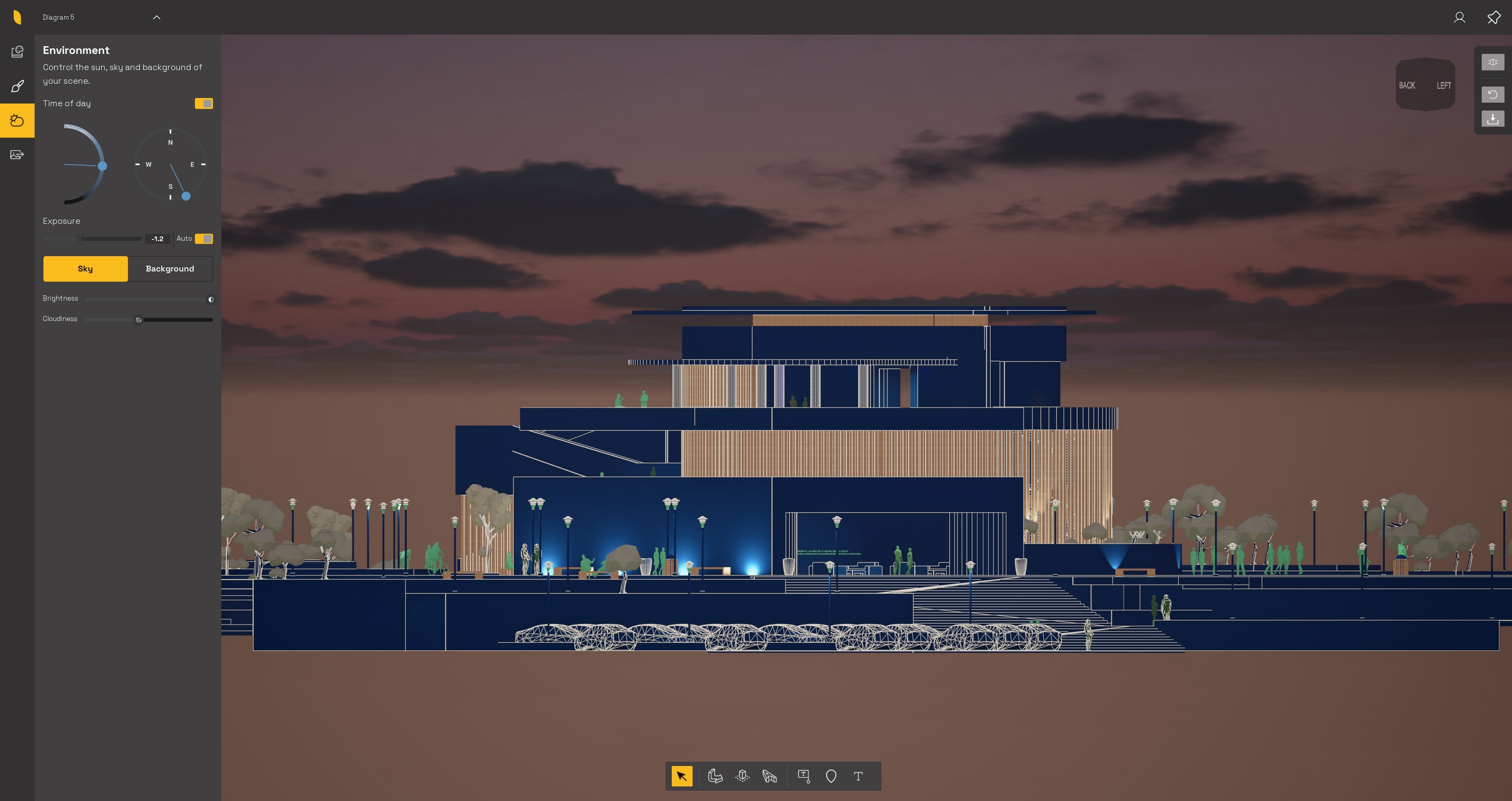
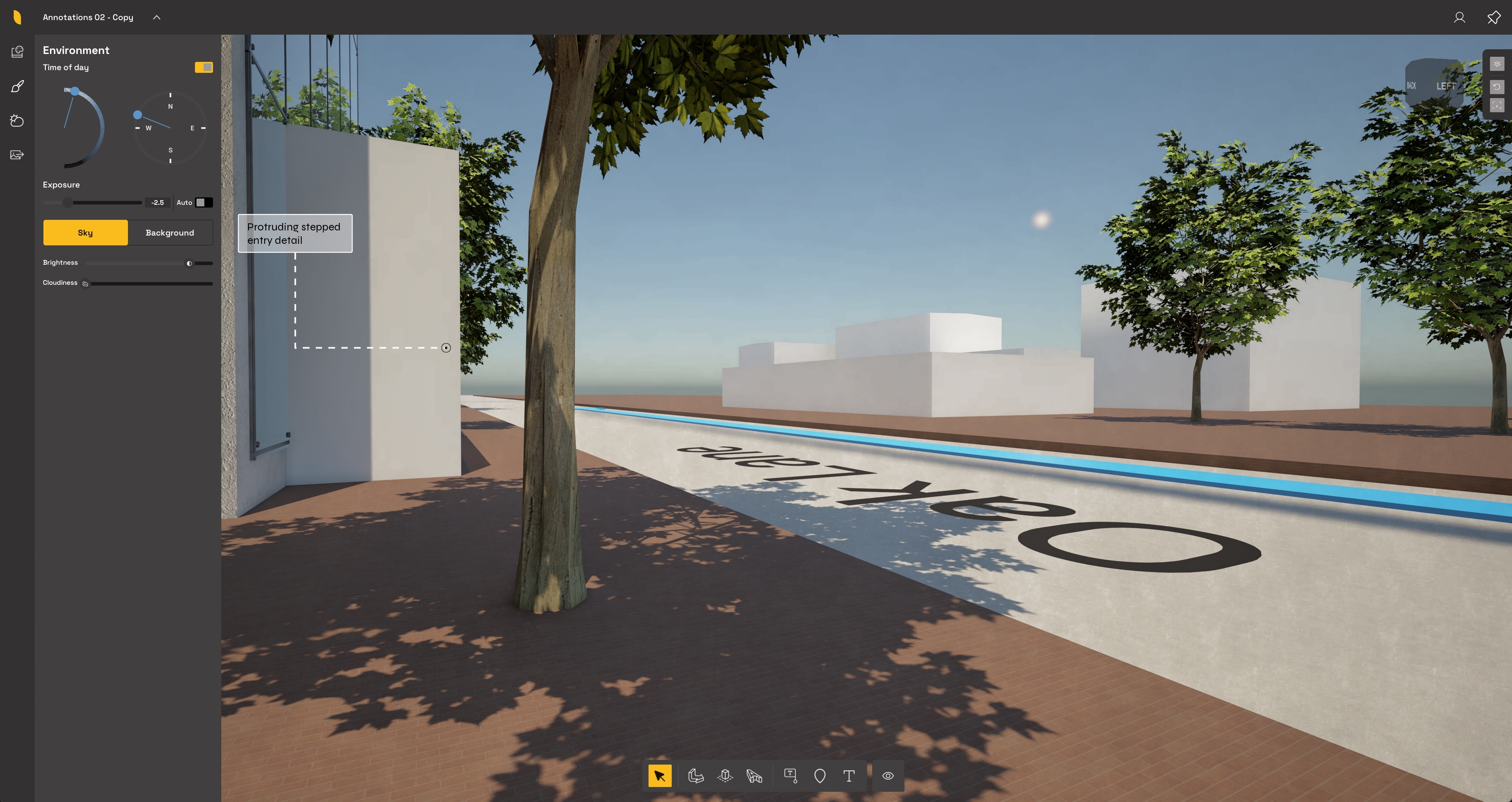
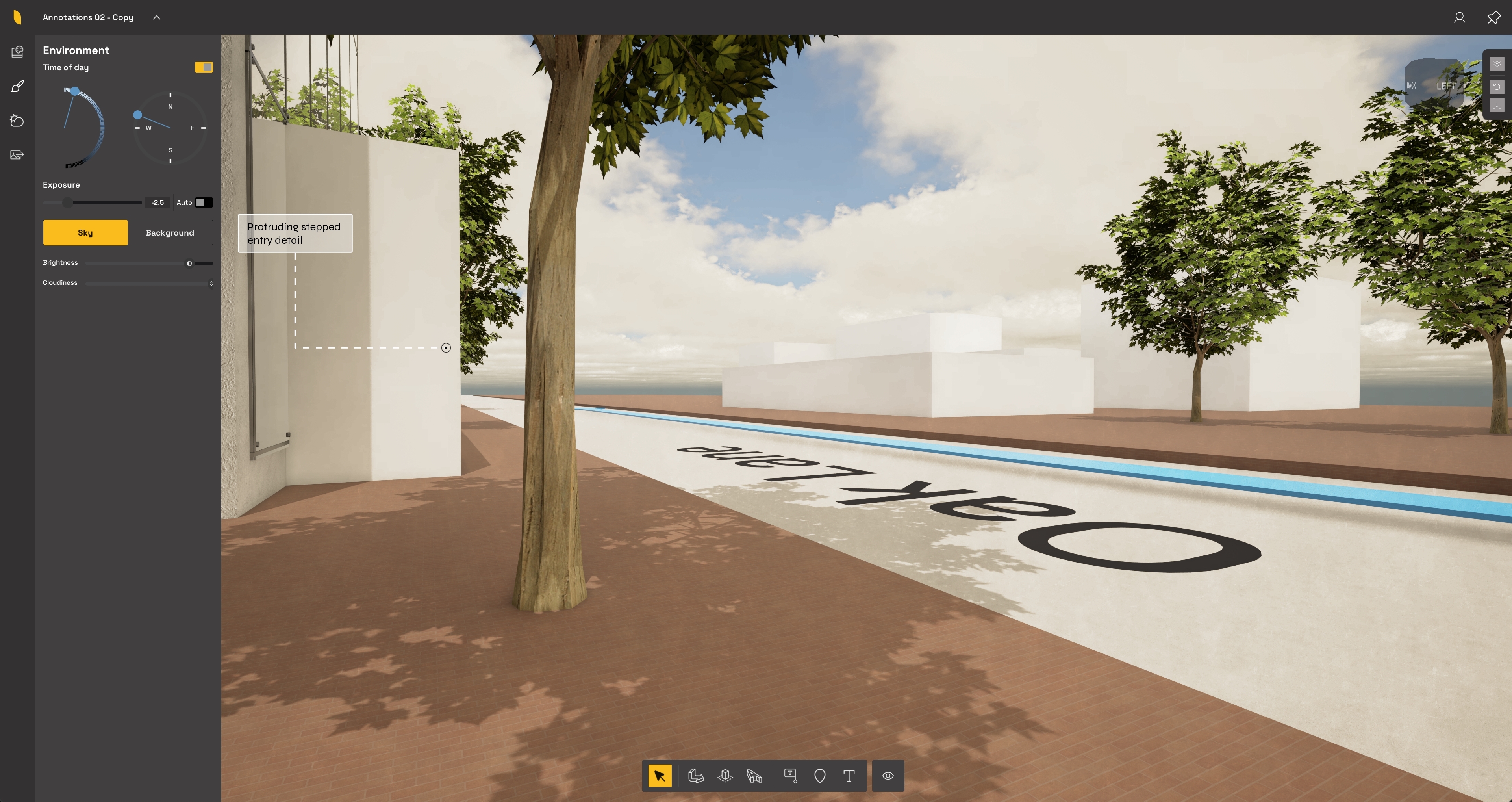
The Environment tab controls the lighting and sky settings for your Scene, including Time of day, Exposure, Brightness, and Cloudiness.
These controls affect one another, so adjusting one setting can change how the others appear in the final render. For example, changing the Time of day can affect the direction and strength of sunlight, while Exposure, Brightness, and Cloudiness can change how bright, clear, or atmospheric the Scene feels.
Use these controls to improve model visibility, set a specific Time of day, or create a cleaner backdrop that complements your chosen Style.

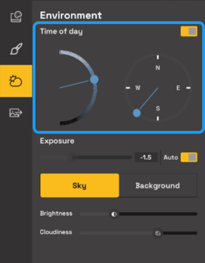
3.1 Time of day:
![]() |
The Time of day controls change the direct lighting across the whole Scene. Use the curved Time of day arc to move through a repeating day-to-night cycle. At the top, the Scene begins at sunrise. As you move down the arc, the sun rises toward midday, then returns to the horizon at sunset. The lower part of the arc represents nighttime, and the bottom connects back to the beginning of the next sunrise. In the Scene, the sun follows a half-circle arc through the sky. The Compass sets a fixed direction for this arc, so it does not rotate as the time changes. As a result, the sun rises and sets in the same direction. These controls affect direct lighting globally. You do not need to select Sky to control the time of day. The Sky option only changes whether a natural sky appears behind your model, instead of a solid-color Background. Use the toggle to turn Axogram’s Time of day lighting on or off. Turn it off if you want Axogram to follow the sun and shadow settings from your CAD software instead. |
To use your CAD software’s own sun and shadow settings, turn off the Time of day toggle in Axogram. Axogram will then follow the sun position provided by the host CAD application instead of using Axogram’s direct time-of-day controls.
Turn Time of day back on when you want to control the sun directly in Axogram again.
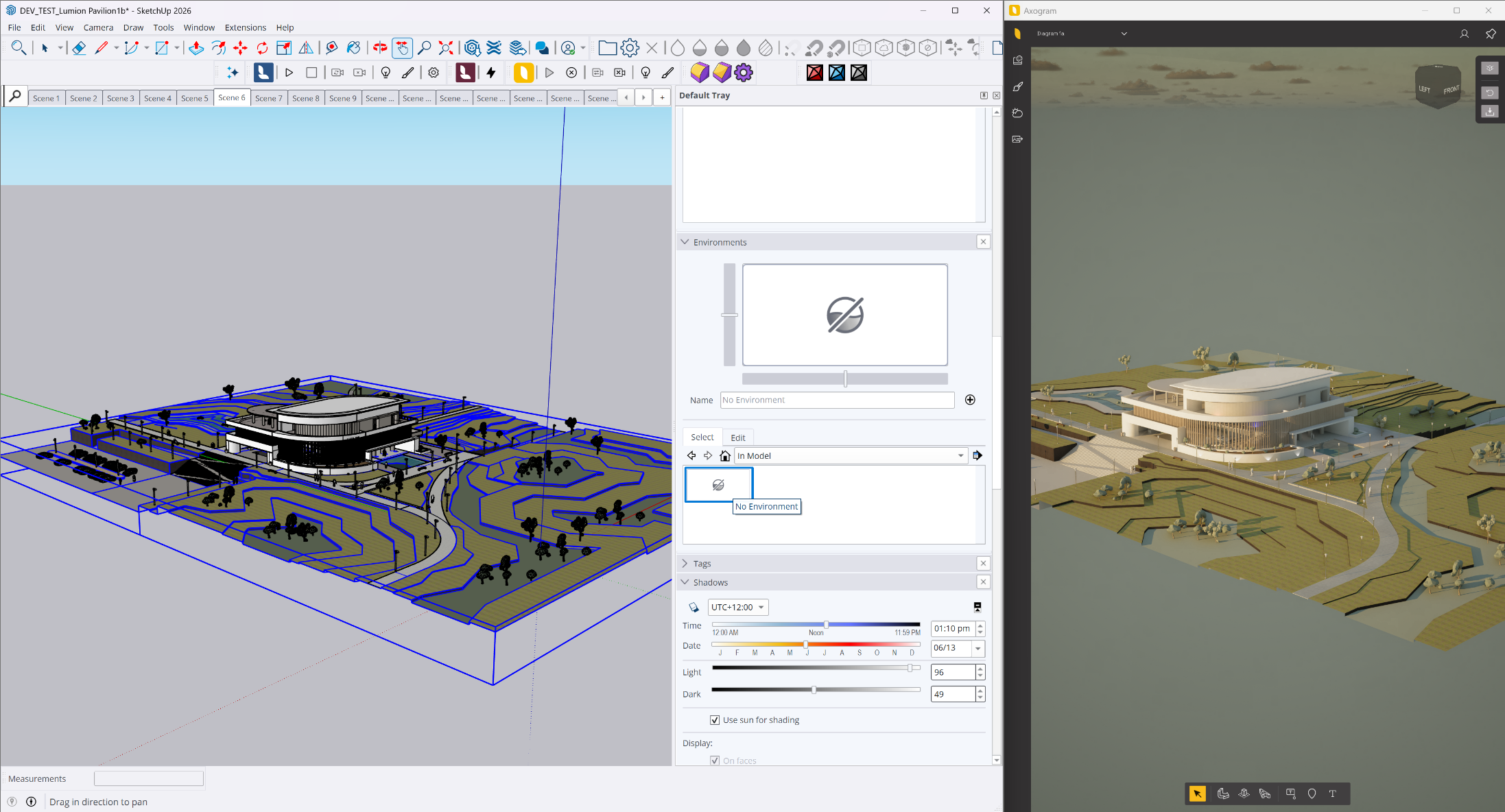
3.1.1.1 SketchUp’s Sun Settings:
In SketchUp, use the Shadows panel to adjust the model’s sun and shadow settings. SketchUp can calculate shadows using the model’s location, orientation, time zone, date, and time.
Open SketchUp’s Shadows controls, then adjust the Time and Date settings to change the sun position. You can also use the shadow display options to control how shadows appear in the SketchUp model.
-
External Link: SketchUp's real-world shadows

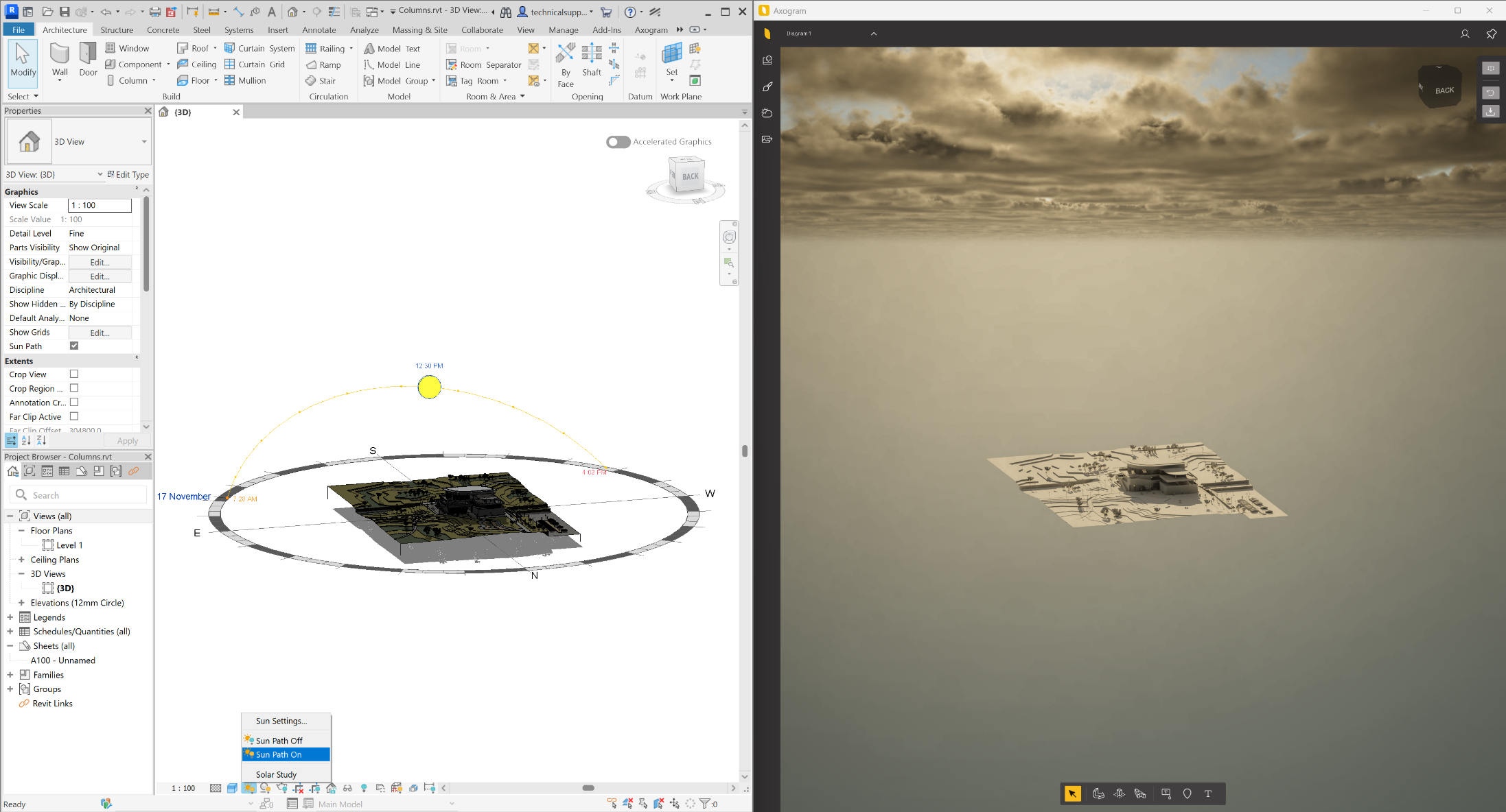
3.1.1.2 Revit's Sun Settings:
In Revit, use the Sun Path and Sun Settings controls for the active view. For best results, turn on both the sun path and shadows in a 3D view.
On the View Control Bar at the bottom left of your screen, turn on Sun Path. You can then use the sun path controls, or open Sun Settings, to define the sun position by date, time, and project location. Revit also allows sun positions to be set using azimuth and altitude values.
- External Link: About Sun Settings
- External Link: Revit: Display Sun and Shadows

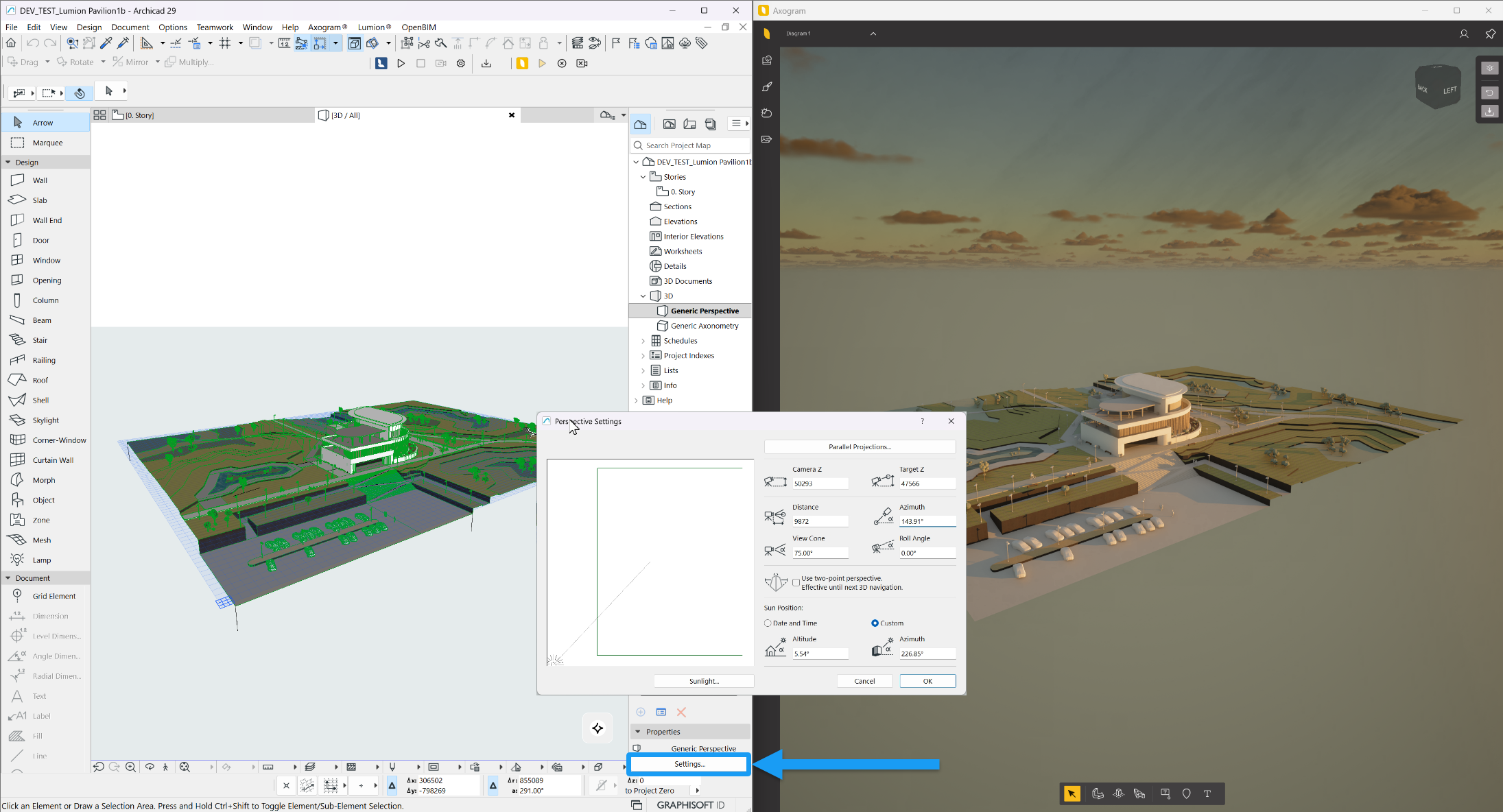
3.1.1.3 ArchiCAD's Sun Setting:
In ArchiCAD, open the sun settings from the 3D projection or camera settings. Go to View > 3D View Options > 3D Projection Settings, or hold #Ctrl# + #Shift# + #F3#, or click Properties in the bottom right of the ArchiCAD screen, then adjust from that window. .
The Sunlight window does not have any affect on Axogram's display, it only controls the viewport in ArchiCAD.
Use these settings to adjust the project’s sun position, including date, time, project location, sun azimuth, and sun altitude. After applying the changes, Axogram will reflect the updated sun position.
- External Link: Dialog Box - Sun

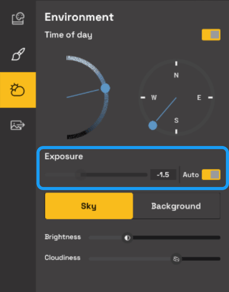
3.2 Exposure:
![]() |
Enable Auto to let Axogram balance the Exposure automatically, or turn it off when you want to set it manually. |
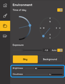
3.3 Sky Settings:

3.3.1 Brightness:
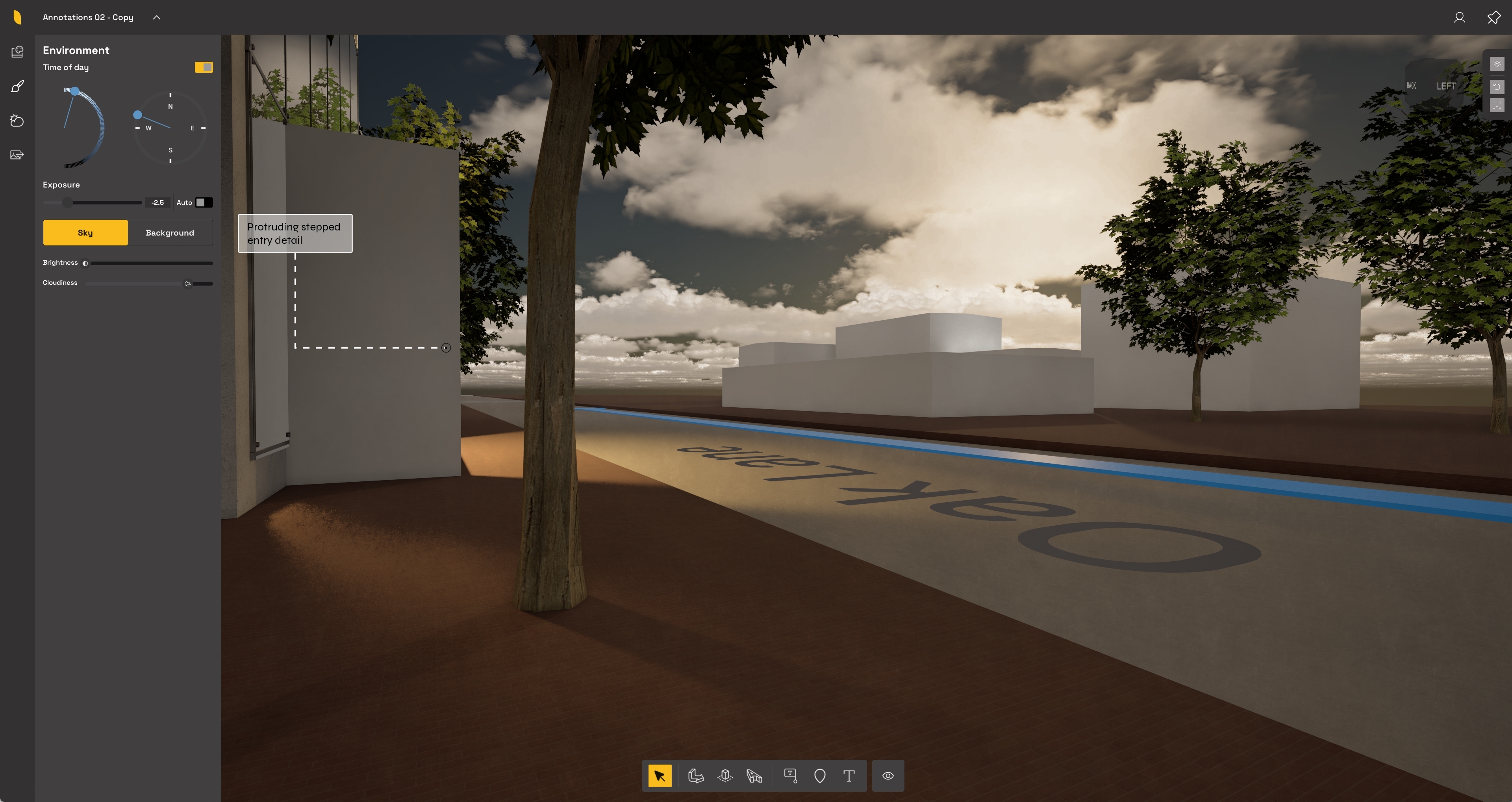
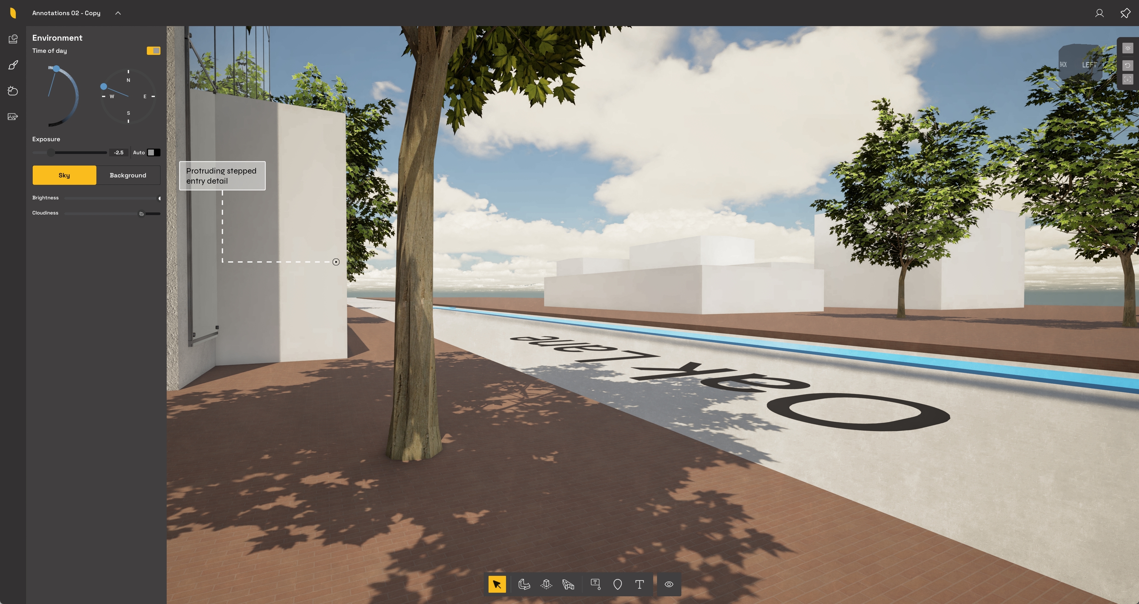
Brightness controls the intensity of the sky and ambient sky lighting. It is influenced by the Time of day setting. For example, the lowest Brightness setting at midday will reduce the sky intensity, but it will not make the Scene look like nighttime.
Because Brightness is limited by the time of day while Exposure is not, you may need to adjust both together. Use Brightness to keep the sky and ambient lighting believable, then use Exposure to fine-tune the overall render.

3.3.2 Cloudiness:

Cloudiness controls the amount of cloud cover, ranging from clear skies to fully overcast conditions. Increasing Cloudiness can make the lighting feel more ambient and diffuse, while reducing the strength of direct sunlight and shadows.
Because this can change the brightness and contrast of the Scene, you may need to adjust Brightness or Exposure afterward to keep the model and sky balanced.

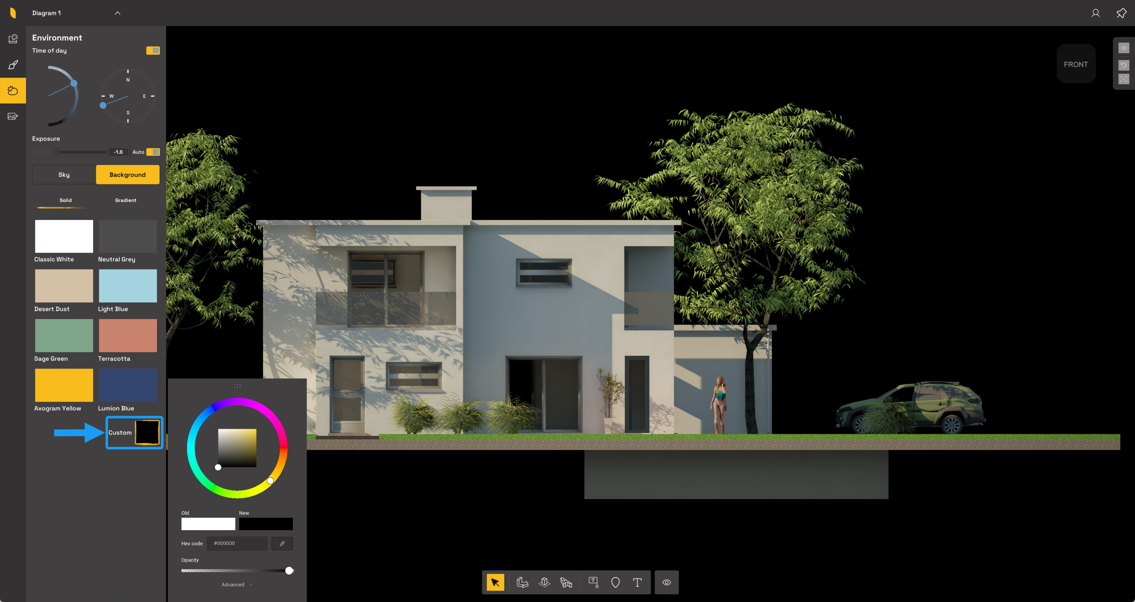
3.4 Background Color Settings
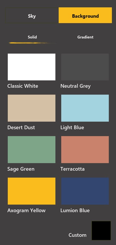
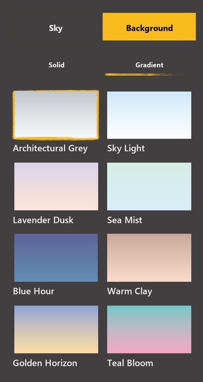
Select Background to replace the natural sky with a simpler backdrop. This can reduce visual distractions, complement your chosen Style, or make the model easier to read.
Solid |
Gradient |
| Applies a single Solid Background color, with 8 default colors to start. This option also lets you use Custom to choose a different color that better suits your Project. | Blends colors to create greater depth. The current gradient is locked and cannot be changed. There are 8 gradients to choose from. |
![]() |
|
3.4.1 Custom Solid Color
If you choose a single color background, your Time of day and sun position settings will be the same and will be used to generate correct lighting for the Ray Trace render.

![]()
The Render To File toolbar is used to export the current model view as an image file. It includes controls for resolution, aspect ratio, Background mode, and the final render command. This toolbar is also movable.

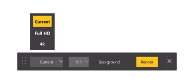
4.1 Resolution Options
The first dropdown controls the render size.

Available options:
-
Current - Exports the view using the current screen/viewport resolution. This option matches what is visible on screen, but it locks the aspect ratio and resolution to the active view. As a result, the aspect ratio control becomes unavailable when Current is selected.
-
Full HD - ( 1920 x 1080 pixels.) Exports at a standard HD resolution. It provides three aspect ratio options.
-
4K - ( 3840 x 2160 pixels ) Exports at a higher standard resolution. It provides the same aspect ratio choices as Full HD.
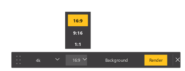
4.2 Aspect Ratio Options
When using Full HD or 4K, the second dropdown lets you select the aspect ratio.

Available options:
-
16:9 - Suitable for landscape images, presentations, screens, and video, most screens support this aspect, landscape.
-
9:16 - An alternative for rotating the 16:9 Landscape to Portrait.
-
1:1 - Square, based on the width dimension of the Resolution.
When Current is selected, the aspect ratio is fixed to the current viewport and cannot be changed.
4.3 Background Option
The Background control can be used to toggle the render background. When enabled, the render uses the visible background.
When disabled, the Background is made transparent. In the current renderer, transparent background previews will appear fully black, even
though the exported image is using transparency.
4.4 Rendering
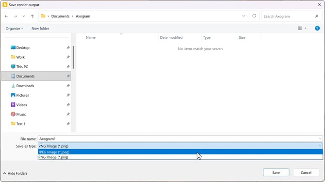
Press Render to begin exporting the image. Enter a file name and folder location to save the file.

File formats for images are .JPG and .PNG.
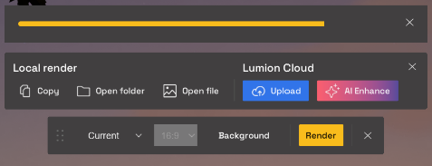
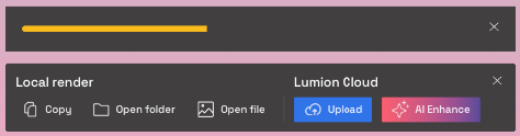
Once you hit Save, a progress bar appears while the render is being generated. The file name is shown during this process.

After the render is complete, a result toolbar appears with the following options:

- Copy: Copies the rendered image to the clipboard. From there, paste it into a client email or other document for a client or for internal review.
-
Open folder: Opens the folder where the rendered image was saved. The rendered file's saved location is shown in the tooltip when hovering over it.
-
Open file: Opens the rendered image directly. The rendered file's name is shown in the tooltip when hovering over it.
Lumion Cloud:
- Upload: Uploads and opens directly in Lumion Cloud. You will see a loading bar once the image has been rendered and begins to upload.

-
AI Enhance: Uploads and opens directly in Lumion Cloud's AI Enhance section.
- Close: Closes the result toolbar.
The rendered file is saved to the output location shown in the tooltip when hovering over the Open folder.
5. Saving and Managing Diagrams
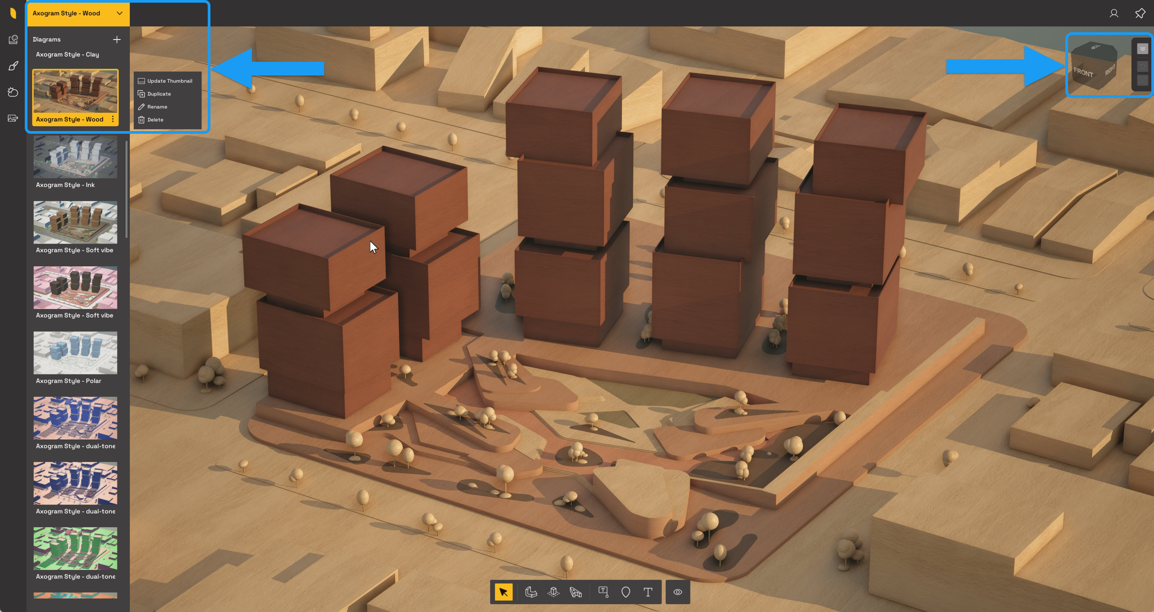
Each Diagram maintains its own camera view, Styles, Environment settings, Annotations, and Action Shapes, allowing you to quickly switch between different looks and design options when presenting or reviewing ideas with clients. The Diagrams panel is located on the left side of the Axogram interface. Use it to create, rename, duplicate, delete, reorder, and manage your saved Diagrams.
Important: Axogram does not create a separate project file. Your Diagrams are saved with your CAD project file.
When you save or share the CAD project file, the Axogram Diagrams are included with it. Another user can access the Diagrams when they open the project and sign in with a Lumion Account that has access to Axogram. A free Axogram account is sufficient.
To create a new Diagram, click the #+# button in the Diagrams panel.
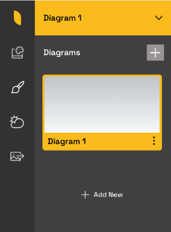
The new Diagram is added to the bottom of the list and uses your current view as its thumbnail. You can then enter a name for the Diagram. This is especially good for when you want to compare styles and combinations while keeping the exact camera view locked in, or creating a slight variation without having to do many changes.
To manage an existing Diagram, click the three dots on the right of its tile to open Manage Diagram.
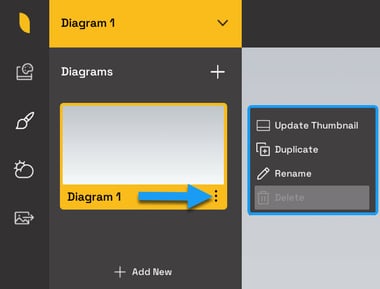
From here, you can:
- Update Thumbnail: Updates the thumbnail using the current view.
- Duplicate: Creates a copy of the Diagram.
- Rename: Changes the Diagram name.
- Delete: Deletes the Diagram.
You can also click and drag Diagram tiles to reorder them in the list.
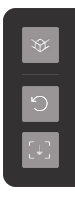
5.1 Reset and Save Camera View
The Reset Camera View and Save Camera View controls are located on the right side of the Axogram interface.
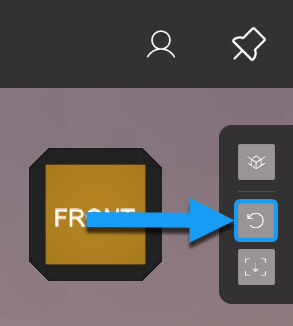
5.1.1 Reset View:
Use Reset Camera View to restore the camera to the saved camera position for that diagram. This is useful if you move around the Scene while editing and want to return to the same view before comparing style, environment, or render changes.
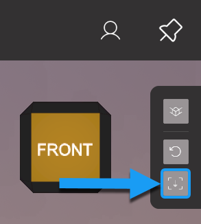
5.1.2 Save Camera View:
Use Save Camera View to save the current camera position for the open diagram that has been selected.
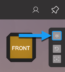
Camera Projection: Perspective or Orthographic
Use the camera and view controls to adjust how you see the Scene before customizing styles or environment settings, or rendering the final image.

Toggle/change between Perspective camera view
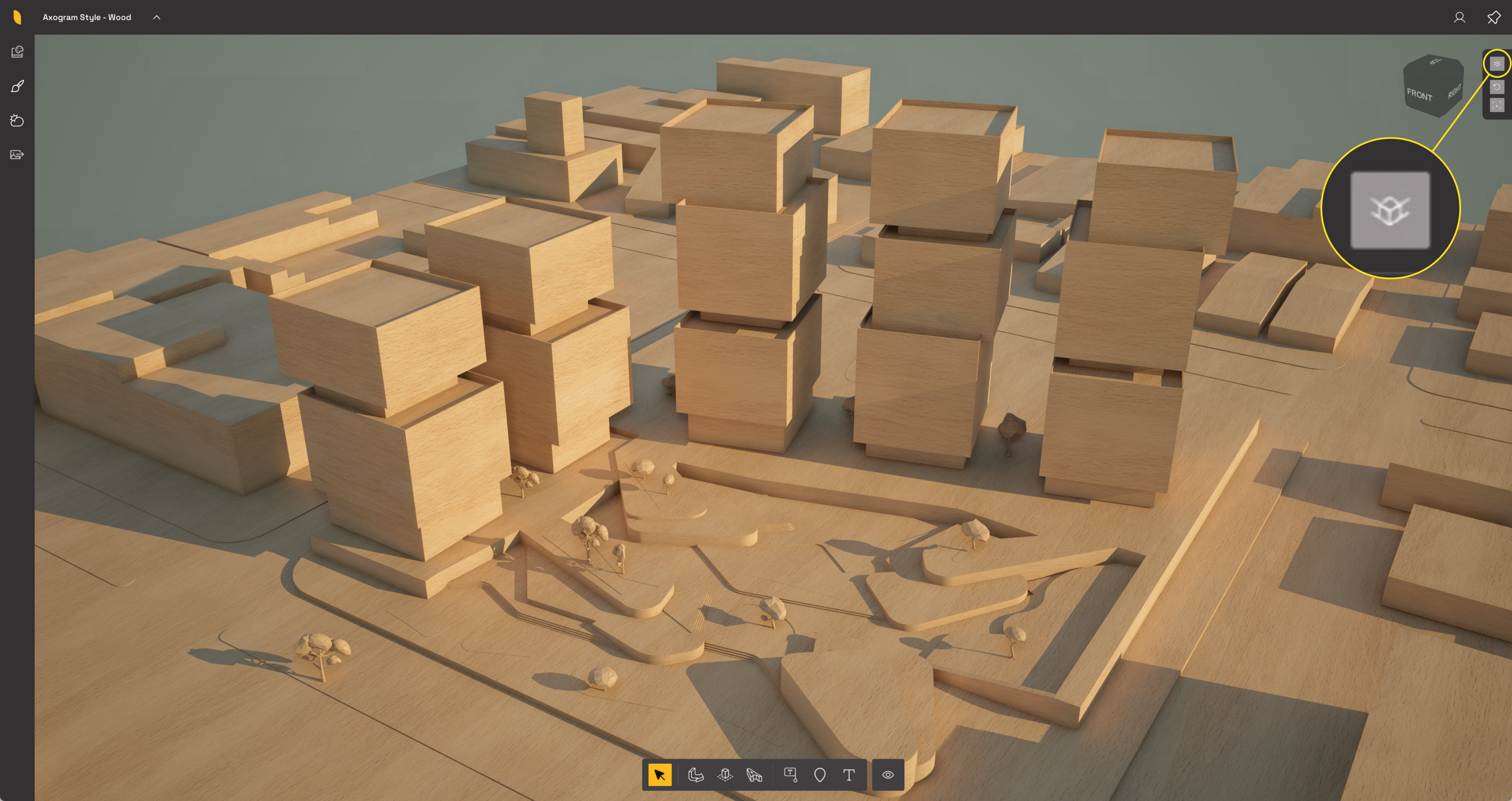
or Orthographic camera view ![]()
6.1 Orthographic View:
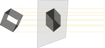
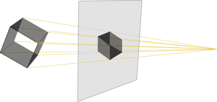
Removes perspective depth from the camera view. Objects keep a more consistent size, even when they are farther from the camera, and vertical lines stay straight on the screen. This makes front, side, top, and diagram-style views easier to read.


6.2. Perspective View:
Shows depth, so objects closer to the camera appear larger. This is useful when you want a more natural 3D view.


6.3 Field of View (FOV) Setting

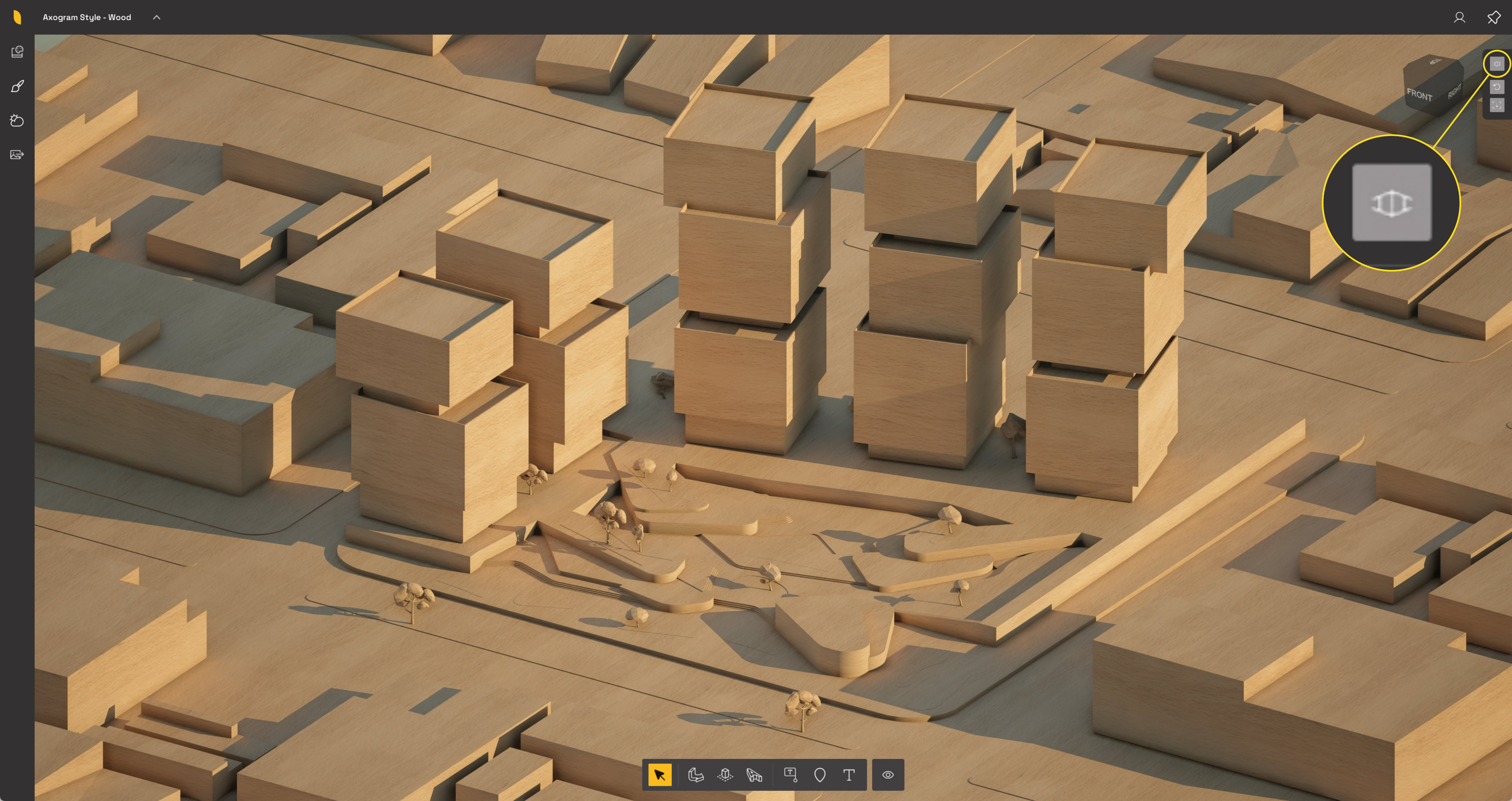
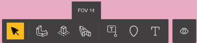
(The Field of View (FOV) indicator is located on the annotations toolbar shown above)
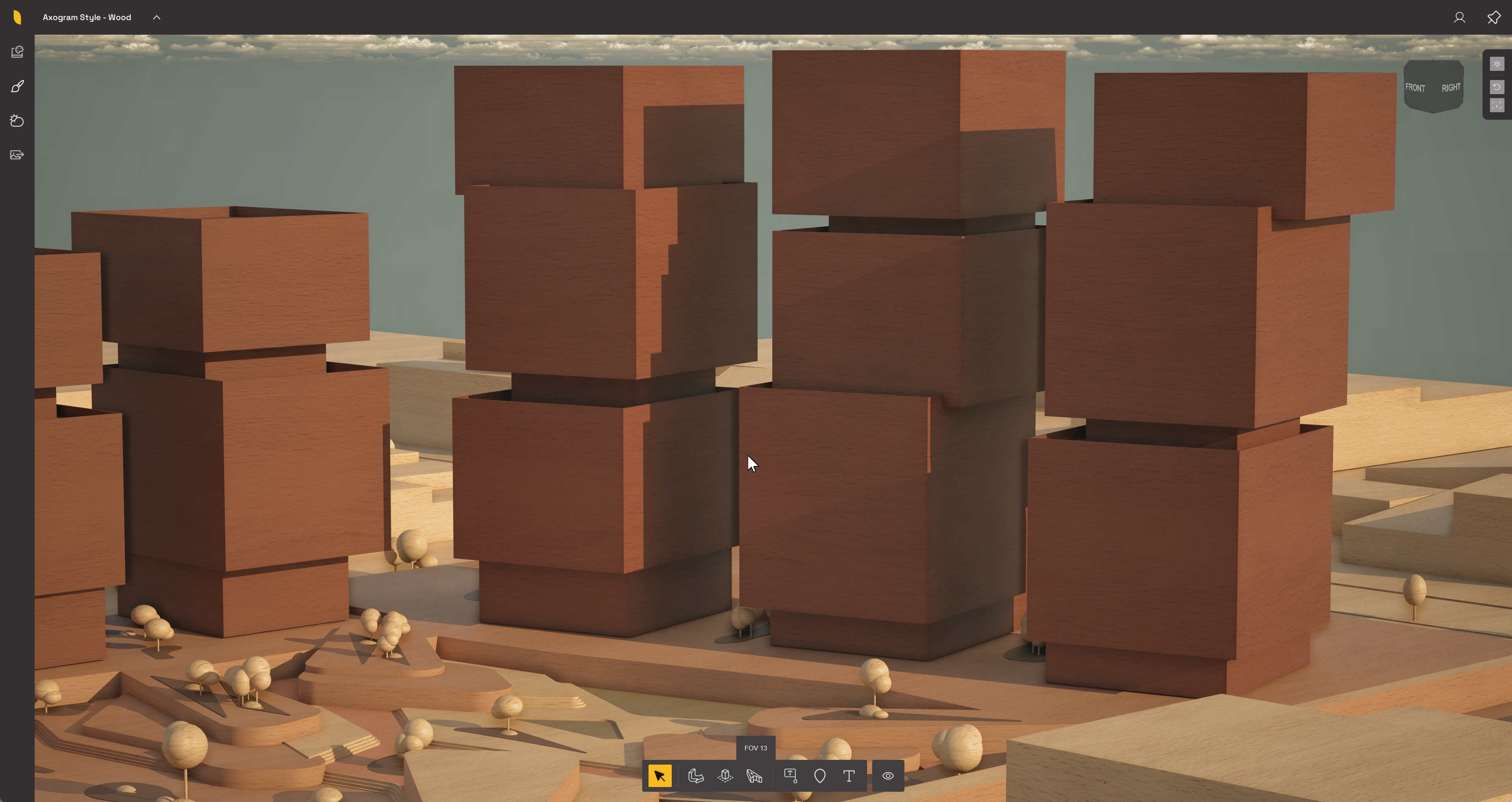
Use Field of View (FOV) to change how wide or narrow the camera view appears. FOV changes the camera lens angle, not the camera position. A higher FOV shows more of the Scene, but can make nearby objects look more stretched or exaggerated. A lower FOV shows less of the Scene and can make the view feel flatter or more focused.
FOV is different from zoom. Zoom moves the view closer to or farther from the model. FOV changes how much of the Scene fits inside the camera view.
Low FOV

High FOV

You can use the mouse wheel in two ways:
-
Scroll normally to zoom in or out, or
-
Hold #Ctrl# while scrolling your #Middle Mouse Button# to adjust the FOV.
To learn how to use the other tools in this toolbar to edit and annotate diagrams, such as annotations, markers, 3D Text, 3D Arrows, and Zones, see:
- Knowledge Base: How do you annotate diagrams in Axogram?
For the full list of camera and navigation shortcuts, see
-
Knowledge Base: Keyboard Shortcuts in Axogram
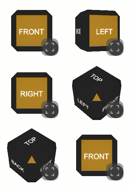
Use the Camera Cube to switch to facing straight, halfway, or angled camera views. The cube has more clickable view positions than the keyboard shortcuts.
Click Area |
Number of Views |
Views |
| Faces | 6 | Front, Back, Left, Right, Top, Bottom |
| Edges | 12 | Top-Front, Top-Back, Top-Left, Top-Right, Bottom-Front, Bottom-Back, Bottom-Left, Bottom-Right, Front-Left, Front-Right, Back-Left, Back-Right |
| Corners | 8 | Top-Left-Front, Top-Right-Front, Top-Left-Back, Top-Right-Back, Bottom-Left-Front, Bottom-Right-Front, Bottom-Left-Back, Bottom-Right-Back |
Click and hold the left mouse button to move/rotate the Camera Cube to reposition the view of the camera for any view. This works for both Orthographic and Perspective cameras views and can also be adjusted manually with your mouse.
See section 2 for a full list of shortcuts for the main 9 views in this article:
- Knowledge Base: Keyboard Shortcuts in Axogram
Example: Front CHANGE UP SCREENSHOT
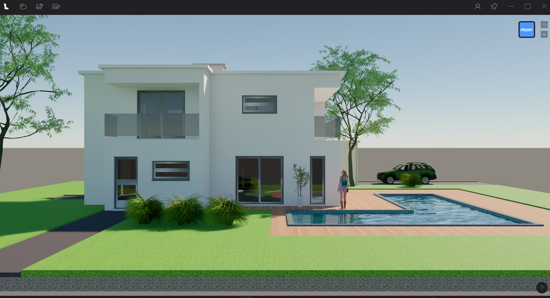
Example: Top right:
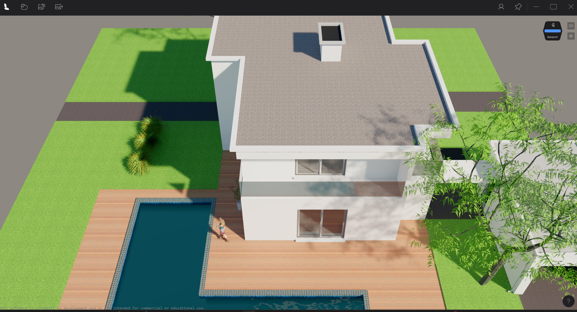
See Also:
-
Knowledge Base: How do you download and access Axogram?
-
Knowledge Base: Keyboard Shortcuts in Axogram
-
Knowledge Base: Axogram Release Notes