

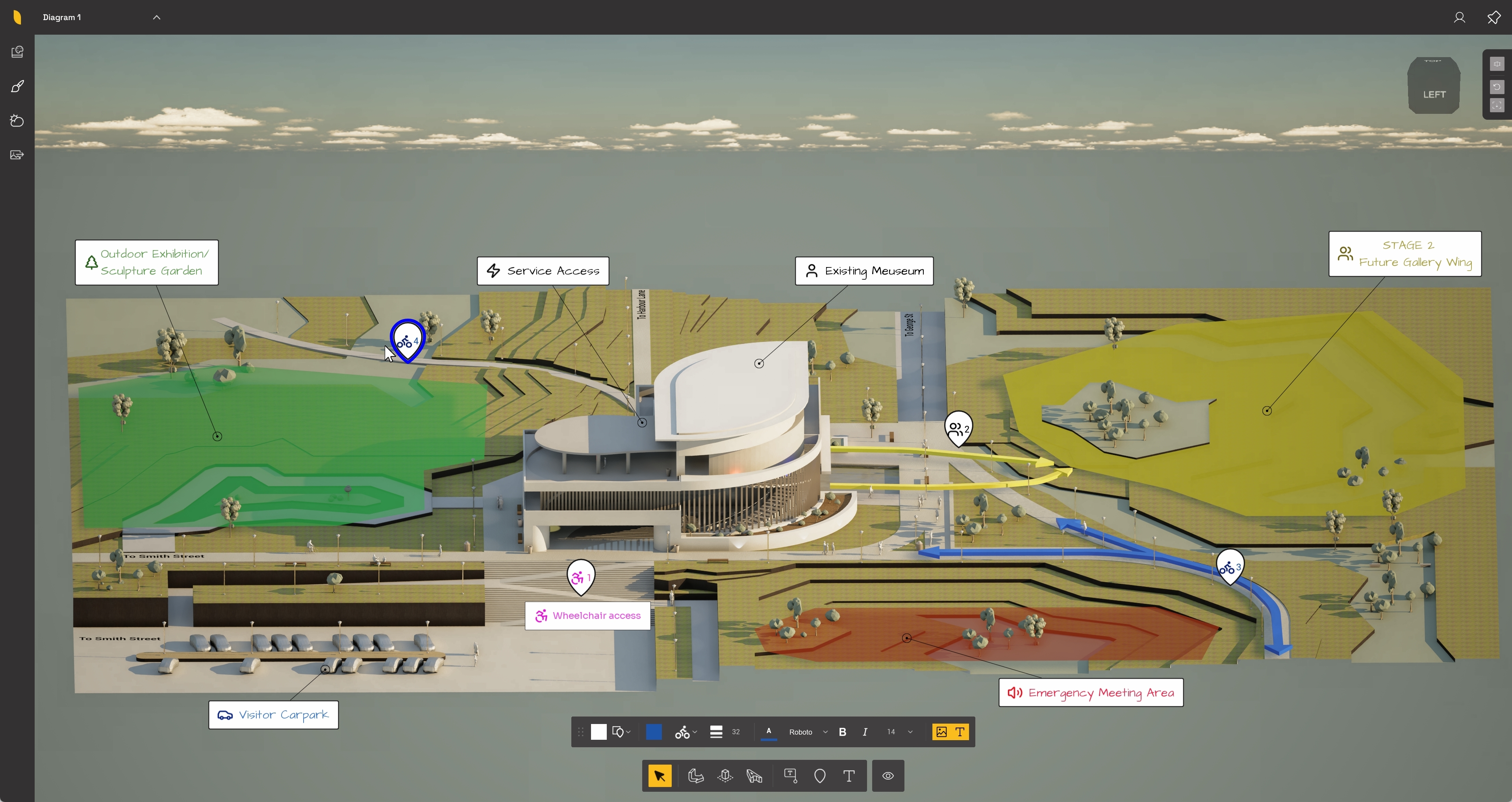
The bottom Annotations toolbar stays visible while you work with annotations. Each creation tool can then have its own contextual settings toolbar, which appears when you switch back to %%Select%% and select an existing element.
Menu:
For tools used to customize the appearance of a diagram, adjust display settings, or render an image, see:
-
Knowledge Base: How do you customize and render a Diagram in Axogram?
For a full list of camera/navigation and keyboard shortcuts, see:
- Knowledge Base: Keyboard Shortcuts in Axogram

The Annotations toolbar contains the tools used to add and manage annotation elements in your %%Scene%%. These tools let you select existing annotation elements, create %%Flow Lines%%, add %%Zones%%, place %%3D Text%%, add %%Annotations%%, place %%Markers%%, add %%Text%%, and control which annotation tools are visible in the toolbar.
The toolbar includes the following tools, from left to right:
- Select - selects existing annotation elements so they can be edited.
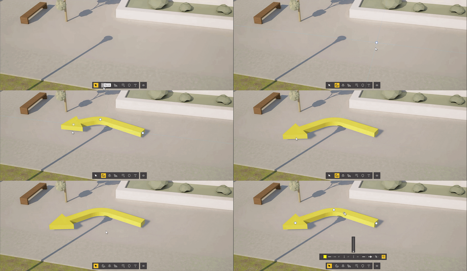
- Flow Line - creates flow lines (arrows) in the model.
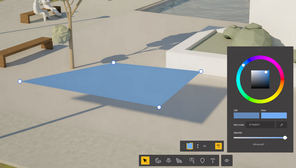
- Zones - creates zone or adjustable shape annotation elements.
- 3D Text - places text directly in the ground.
- Annotation - adds an annotation label.
- Marker - places a variety of markers in the model.
- Text - adds a text annotation to the screen. The position is static.
- Set tool visibility - shows or hides tools in the annotations toolbar.
Most annotation tools follow the same basic workflow. First, choose the tool you want to use, then place or draw the annotation element in the model. After the element has been created, press #Enter# to finish the action.
To edit an annotation object after it has been created, choose the %%Select%% tool and select the object in the %%Scene%%. The %%Select%% tool must be active, and the element must be highlighted, before its settings can be edited. The settings toolbar changes depending on the type of annotation object selected.







The %%3D Text%% tool is used to place horizontal text flat on the ground. You can only rotate on the ground axis. After you create the text, you can select it and edit it using the 3D Text settings toolbar.
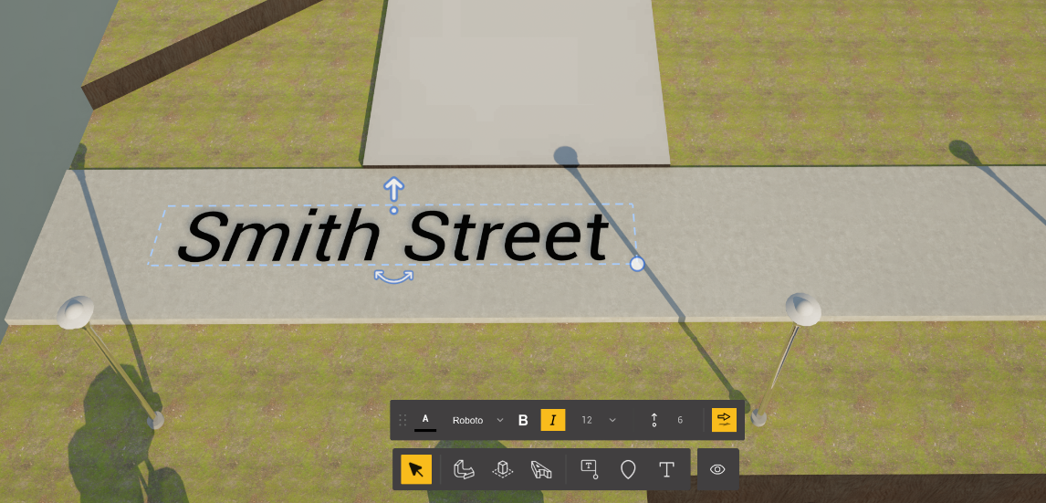
5.1 Settings for 3D Text
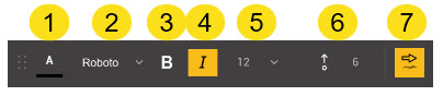
The %%3D Text%% settings toolbar includes the following options, from left to right:
- Text color - changes the color of the selected %%3D Text%% and opens the color picker.
- Font - changes the font used for the selected %%3D Text%%. Available fonts include Roboto, Architects Daughter, Inter, Sora, and Sign.
- Bold - applies or removes bold formatting (not available for every font)
- Italic - applies or removes italic formatting (not available for every font)
- Font size - adjusts the size of the selected %%3D Text%%. You can set the font size from 12 to 30. (This can also be adjusted by the scale feature when manually editing)
- Offset - adjusts the height of the text up or down. You can adjust the offset using the slider or by entering a value.
- Shadow - enables or disables shadow for the selected text.
5.2 Adding 3D Text

To add 3D Text:
- Select the %%3D Text%% tool from the annotations toolbar.
- Click in the %%Scene%% where you want to place the text.
- Type the text you want to add.
- Press #Enter# to finish creating the %%3D Text%%.
After you create the text, you can select and edit it.
5.3 Editing 3D Text

To edit 3D Text:
- Select the %%Select%% tool.
- Click the %%3D Text%% in the model so it is highlighted.
- Use the %%3D Text%% settings toolbar to adjust the selected text (refer to section 5.1 for more info)
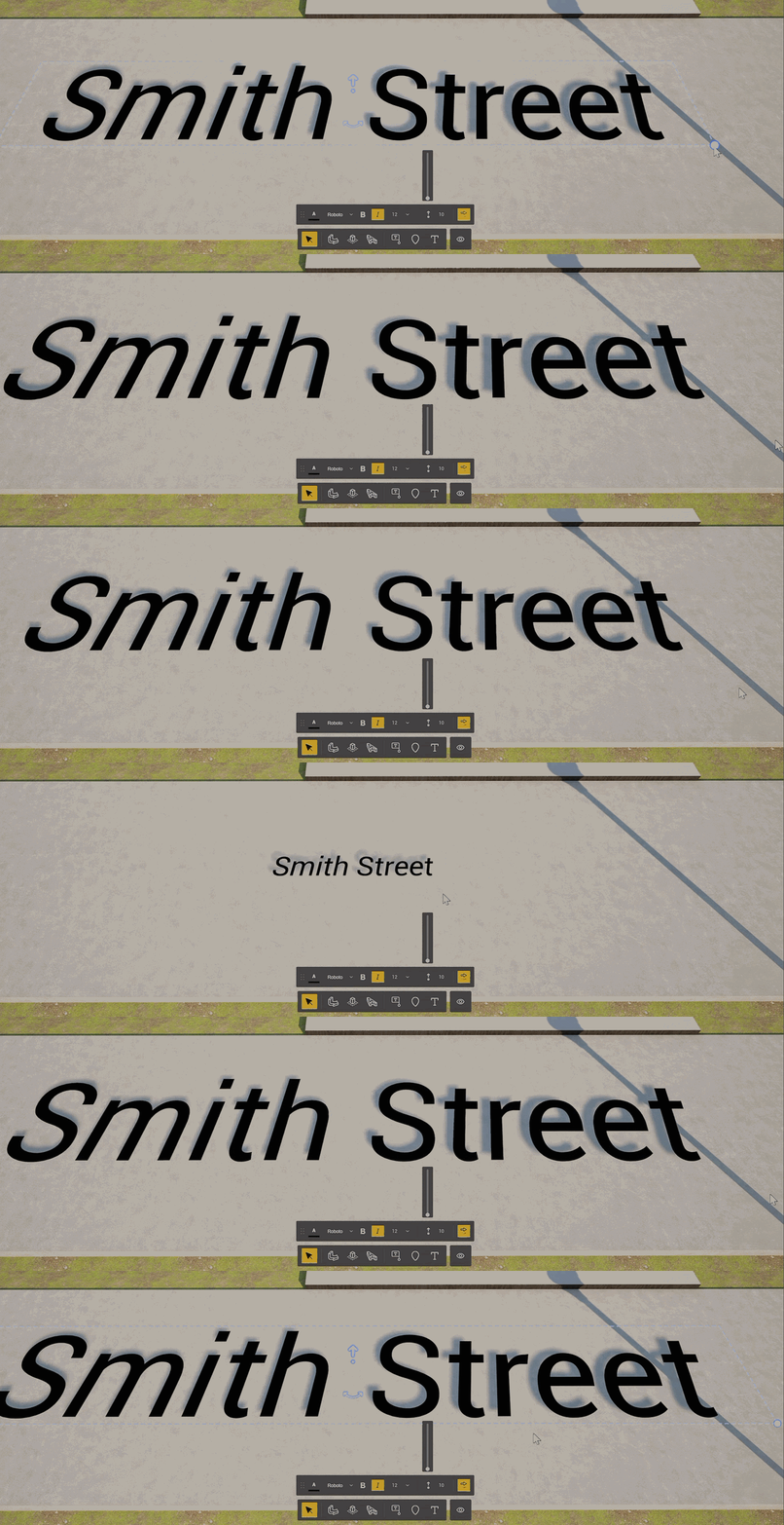
You can edit 3D Text manually in the %%Scene%%:
-
Use the available handles to move the text up or down by using the straight arrow:
-
Rotate it on the horizontal plane by using the curved arrows:
.gif?width=670&height=217&name=ezgif.com-video-to-gif-converter%20(1).gif)
-
Or adjust its scale from the corner by clicking the white dot:
Tip: Auto-snapping helps you line up with other annotation objects and keep labels, text, etc. square and aligned.
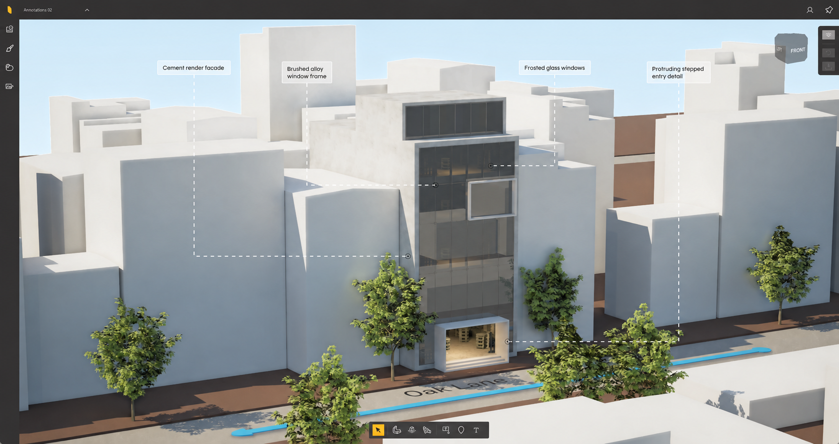
The Annotation tool is used to add a labeled annotation object to a specific point in the model. An annotation has two main parts: the label and the leader.
The label is the box that contains the annotation text. It stays fixed on the screen.
The leader is the line that connects the label to the selected point in the model. The leader point stays attached to the model. When the camera view changes, the label and leader stay connected, and the leader updates to maintain the connection between the screen label and the model point.
6.1 Adding an Annotation
To add an Annotation:

- Select the Annotation tool from the Annotations toolbar.
- Click in the %%Scene%% to place the leader point.
- Position the annotation label.
- Enter the annotation text.
- Press #Enter# to finish creating the annotation.
After the annotation has been created, it can be selected and edited.
6.2 Editing an Annotation

To edit an Annotation:
- Select the Select tool.
- Click the annotation in the model so it is highlighted.
- Use the label settings toolbar or the leader settings toolbar to adjust the selected annotation.
Annotations have two settings toolbars:
- Label settings - adjust the label box, text, icon, and visibility options.
- Leader settings - adjust the leader line that connects the label to the model point.
6.3 Label Settings

The Annotation label settings toolbar includes the following options, from left to right:
1. Label color - changes the annotation label color and opens the color picker.
2. Outline settings - changes the outline style and thickness. You can set the outline to marker, rectangle, or circle. You can adjust the thickness using the slider or by entering a value, and also the icon color.
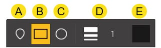
3. Icon color - changes the color of the annotation icon.
The Annotation label settings toolbar includes the following options, from left to right:
1. Label color - changes the annotation label color and opens the color picker.
2. Outline settings - changes the outline style and thickness. You can set the outline to marker, rectangle, or circle. You can adjust the thickness using the slider or by entering a value, and also the icon color.
3. Icon color - changes the color of the annotation icon.
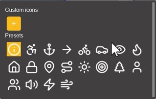
5. Icon Thickness - increases or decreases the thickness of the icon.
6. Text color - changes the color of the annotation text.
7. Font - changes the font used for the annotation text. Available fonts include Roboto, Architects Daughter, Inter, Sora, and Sign.
8. Bold - applies or removes bold formatting.
9. Italic - applies or removes italic formatting.
10. Font size - adjusts the size of the selected %%3D Text%%. You can set the font size from 12 to 30. (This can also be adjusted by the scale feature when manually editing)
11. Show icon - toggles the annotation icon on or off.
12. Show text - toggles the annotation text on or off.
6.4 Leader settings
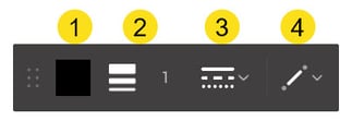
The Annotation leader settings toolbar includes the following options, from left to right:
1. Color - changes the color of the leader line.
2. Thickness - adjusts the thickness of the leader line.
3. Shape - changes the leader line style. The leader can be displayed as a solid, dashed, or dotted line.
4. Direction - changes the leader direction or corner style between the label and the selected point.
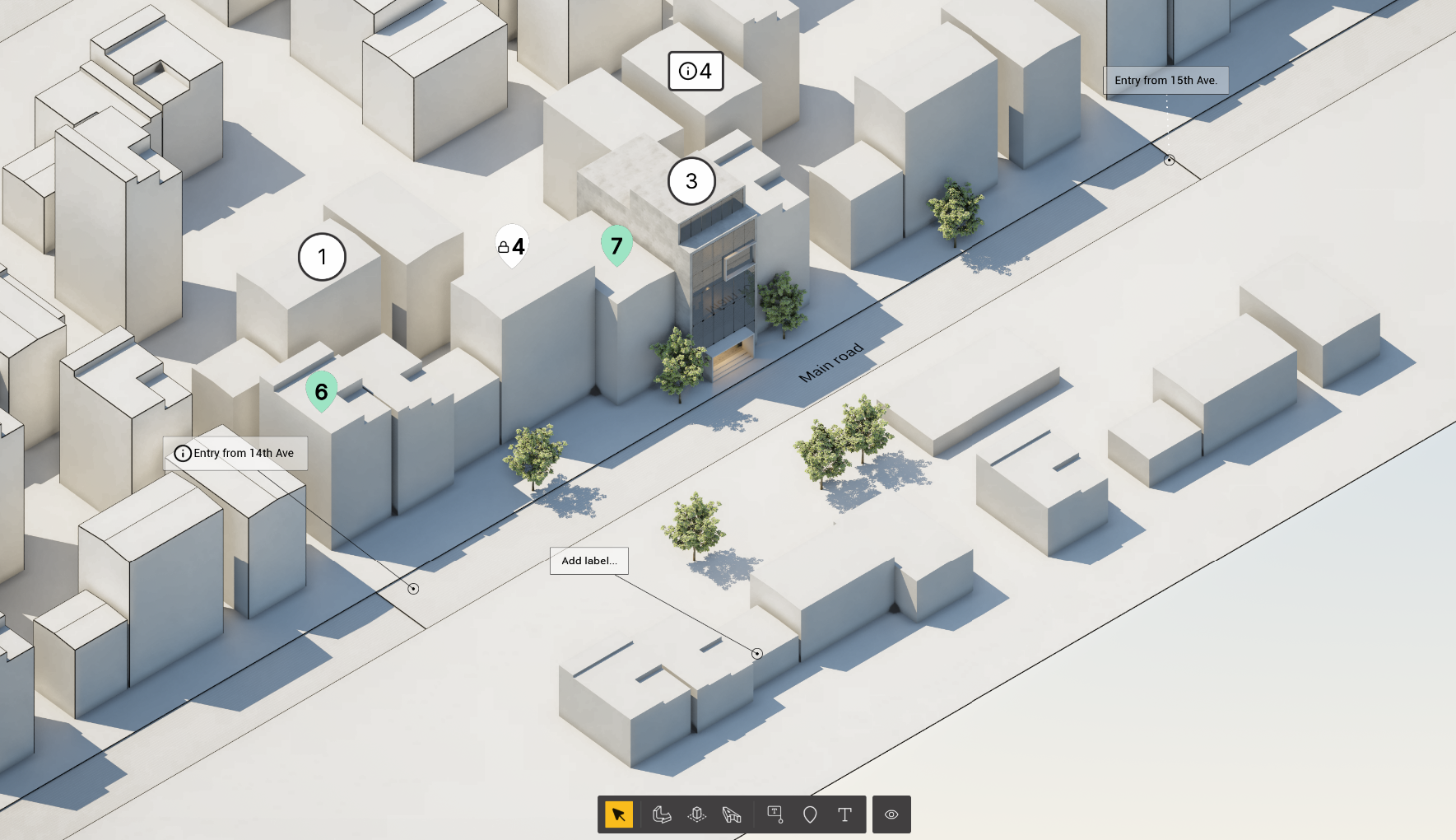
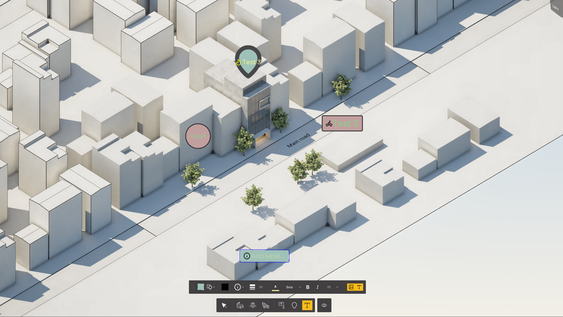
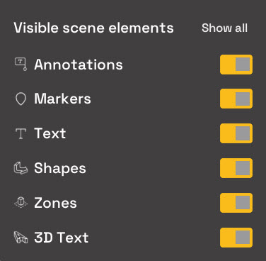
The Set tool visibility button is used to show or hide tools in the Annotations toolbar. This lets you keep the toolbar focused on the annotation tools you need.
Use the visibility toggles to turn individual tools on or off. When you hide a tool, it is removed from the Annotations toolbar. When you show it again, it becomes available in the toolbar.
The Show all option restores all annotation tools to the toolbar.
See Also:
- Knowledge Base: Axogram Release Notes
- Knowledge Base: What kind of computer does Axogram need?
- Knowledge Base: How do you download and access Axogram?