

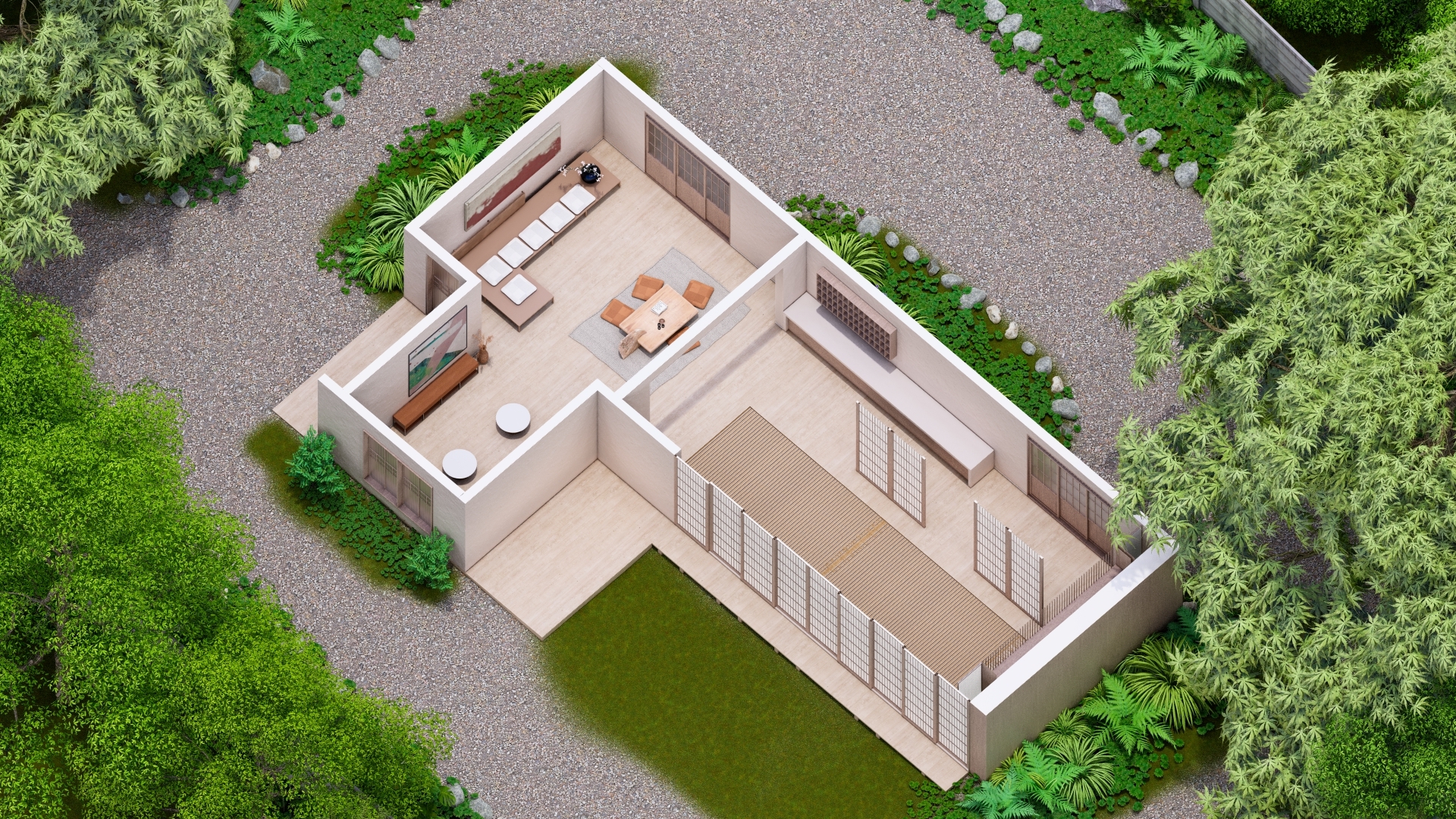
The Clip Plane object allows you to cut through geometry and reveal the interior of your design without modifying the original model. It can be positioned and rotated to create architectural sections, elevations, and cutaway views from different directions. You can also control which Layers are affected, making it possible to section the main building while leaving other Objects visible.
Menu:
In Lumion 2026.0, the Clip Plane was improved with the option to apply a fill or material to the clipped surface, allowing cut geometry to appear solid rather than hollow. See:
- Knowledge Base: Lumion 2026.0: Release Notes Section 1.2: Fill-in Clip Plane for an Imported Model
1. Placing the Clip Plane
1.1: To add a Clip Plane, navigate to Build Mode.
1.2: Select the Utilities category and choose the Place button.
.png?width=640&height=213&name=BuildModeClipping%20(1).png)
1.3: Select the Clip Plane object and place it in your Scene.
.png?width=387&height=711&name=Clipping%20(1).png)
2. Controlling Layer Visibility
By default, a Clip Plane will cut through all objects in your scene. However, you can control which layers are affected.
2.1: Select the Clip Plane using the Select tool.
2.2: In the Object Properties window, you can choose to target All Layers or specific ones, such as Imported Models only. This is useful for cutting through the building structure while keeping furniture or surrounding nature intact.
.png?width=387&height=282&name=ClippingLayers%20(1).png)
3. Adding and Customizing the Fill
The fill option is only available in Lumion 2026.0 and newer versions.
Other objects can still be clipped by the Clip Plane, but a fill will not be generated for their exposed surfaces.
When the Clip Plane intersects an Imported Model, Lumion analyzes the exposed geometry and attempts to generate a surface that closes the clipped section. You can apply a color or material to this surface so the Imported Model appears solid rather than hollow.
Note: Fill generation is optimized for clean, well-formed architectural elements such as walls, floors, and slabs. Results depend on the geometry and complexity of the Imported Model. Large open volumes, overlapping faces, gaps, or highly complex geometry may prevent some clipped areas from generating a fill.
Method A: Using a Simple Color
3.1: With the Clip Plane selected, turn on the Outline toggle and click on the color picker in the properties panel.
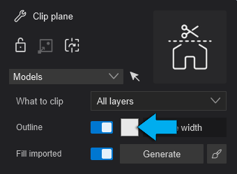
3.2: Choose a color.
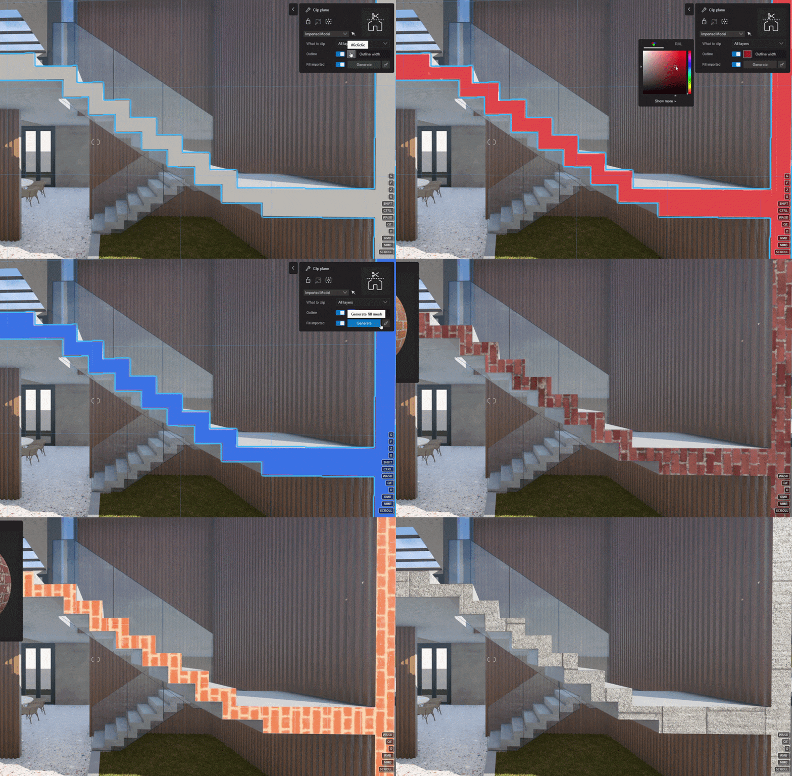
Method B: Applying a PBR Material
3.3: For a realistic finish, you can treat the fill as a material surface.
3.4: Click the Edit Material button for the fill.
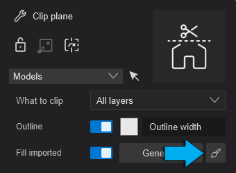
3.5: You can now apply a full PBR Material from the Material Library. This allows you to match the fill to the wall material (e.g., concrete or brick) or make it unique to highlight the cut.
4. Additional Clip Plane options
4.1 Use the Clip Outline in Lumion 12 and newer
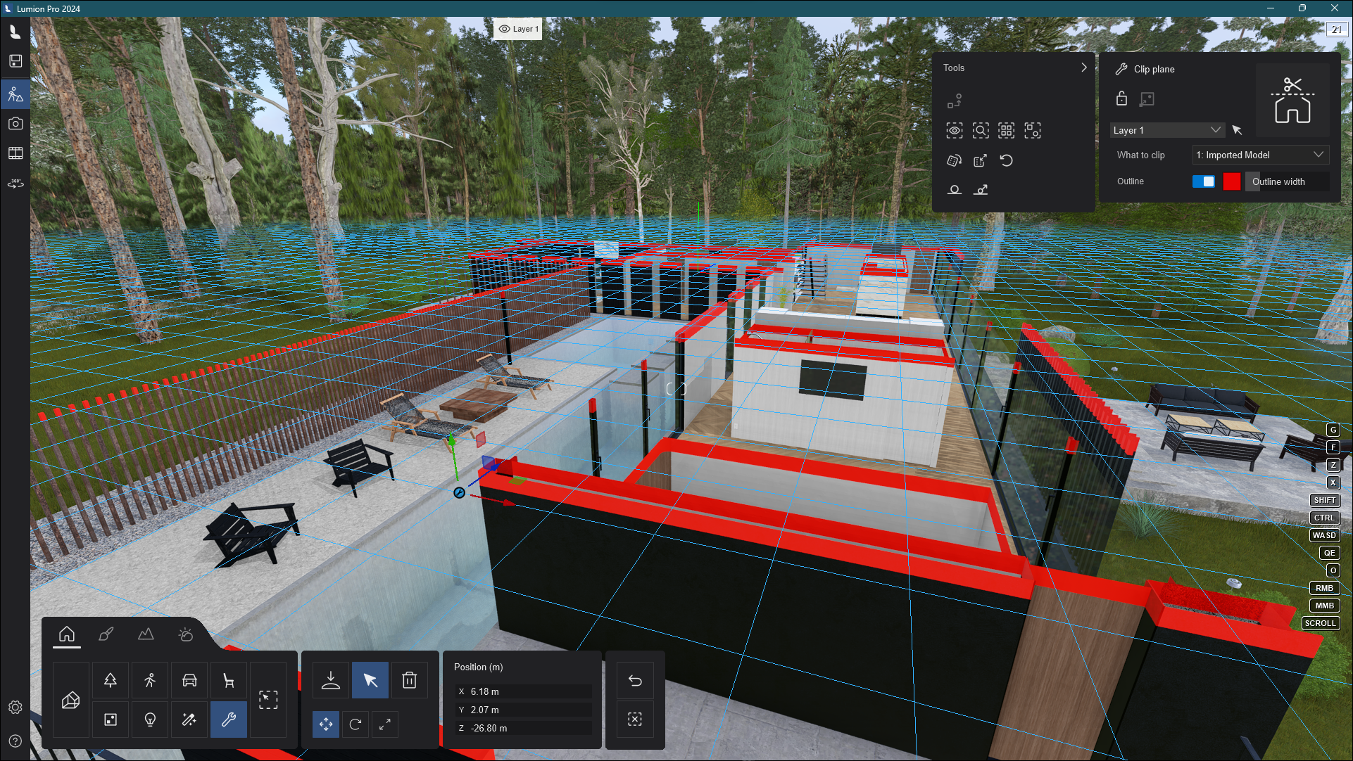
You can use the Clip Outline option to render outlines along the edge of the visible geometry that is clipped. It is possible to set the width and color of the outline as well as which Layer to clip. Geometry that is facing away from the camera, and therefore isn’t visible, won’t have a visible outline.
4.2 Flip the Clip Plane in Lumion 2024.3 and newer 
In Lumion 2024.3, a toggle was added to flip the Clip Plane, making it easier to choose which side is clipped without manually rotating the Object. See Section 3.3:
- Knowledge Base: Lumion 2024: Update to 24.3 - Release Notes
4.3 Animate the Clip Plane
You can also animate the Clip Plane to reveal or hide parts of a building during a construction sequence.
- Knowledge Base: How do you animate the construction process of a building?
4.4 Use Variations and the Variation Control Effect
Consider using the Variations function and the Variation Control Effect to show the clipped version of the model alongside the original version:
- Knowledge Base: How do you make Variations of a model?
- Video Tutorial: Lumion 8: Build Mode - Add model Variations
- Video Tutorial: Lumion 8: Effects - The Variation Control Effect
5. In all versions prior to 2026.0
Unlike the section plane/box function available in Revit and ArchiCAD, the Clip Plane in Lumion does not 'know' whether an object is solid or not, so walls and other solid objects will appear hollow.
Example of hollow walls and floors when using the Clip Plane in Lumion:

Use a section plane or box in your 3D software
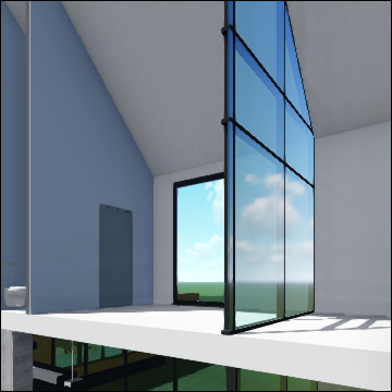
We recommend using the section plane/box functionality in your 3D modeling software if that feature is available, and it caps clipped objects as solid surfaces.
Example of capped walls and floors when using the Section Box tool in Revit:
See section 5.2 How do you fill the spaces in a wall so they look solid or capped?
Section Planes in SketchUp cannot be exported to Lumion, so you will have to use a plug-in:
- External Link: Eneroth Slicer


